Visualizing Aircraft Electrical Systems
Generator Construction Mechanics
The Stator Frame
At the heart of any aircraft generator is a dance between a stationary part and a rotating part. The stationary component, the stator, serves as the fixed frame that holds the main power-generating windings. It's not a solid block of metal. Instead, the stator core is built from stacks of thin, soft-iron plates called laminations. These plates are insulated from each other with a thin varnish coating.
Slotted into this laminated core are the stator windings. In a typical three-phase aircraft alternator, there are three separate sets of windings. They are physically wrapped and positioned around the stator so that they are spatially displaced from each other by 120 degrees. This precise mechanical arrangement is what ensures a balanced, three-phase AC output as the magnetic field sweeps past them.
The Spinning Rotor
The rotor is the moving part, spinning at high speed inside the stator. In most aircraft alternators, the rotor houses the field winding, which creates the magnetic field. Similar to the stator, the rotor core isn't a solid piece of steel. It is also constructed from to minimize the generation of unwanted within the core material. These currents are a byproduct of induction, and if left unchecked, they would create immense heat and waste energy.
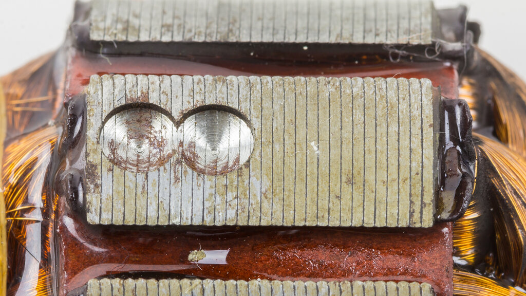
The entire rotor assembly is precisely balanced to ensure smooth operation at thousands of RPM, preventing destructive vibrations within the engine accessory gearbox.
Extracting the Power
Getting electricity from the stationary windings is straightforward. But to create the magnetic field in the rotor, we need to supply it with DC power. This requires a connection between the stationary aircraft electrical system and the spinning rotor. The hardware used for this task is a key difference between AC and DC generators.
In an AC alternator, this is done with a slip ring assembly. Two solid, conductive rings, typically made of copper or brass, are mounted on the rotor shaft but insulated from it. Each ring is connected to one end of the field winding. Carbon brushes, held in a brush gear assembly, ride on these smooth rings to conduct current to the spinning coil.
A DC generator uses a much more complex device: the commutator. Instead of two solid rings, a [{
}] is a single ring composed of many insulated copper segments. Its job is to act as a mechanical rectifier, reversing the connection to the brushes every half rotation. This action flips the output polarity, converting the internally generated AC into external DC.
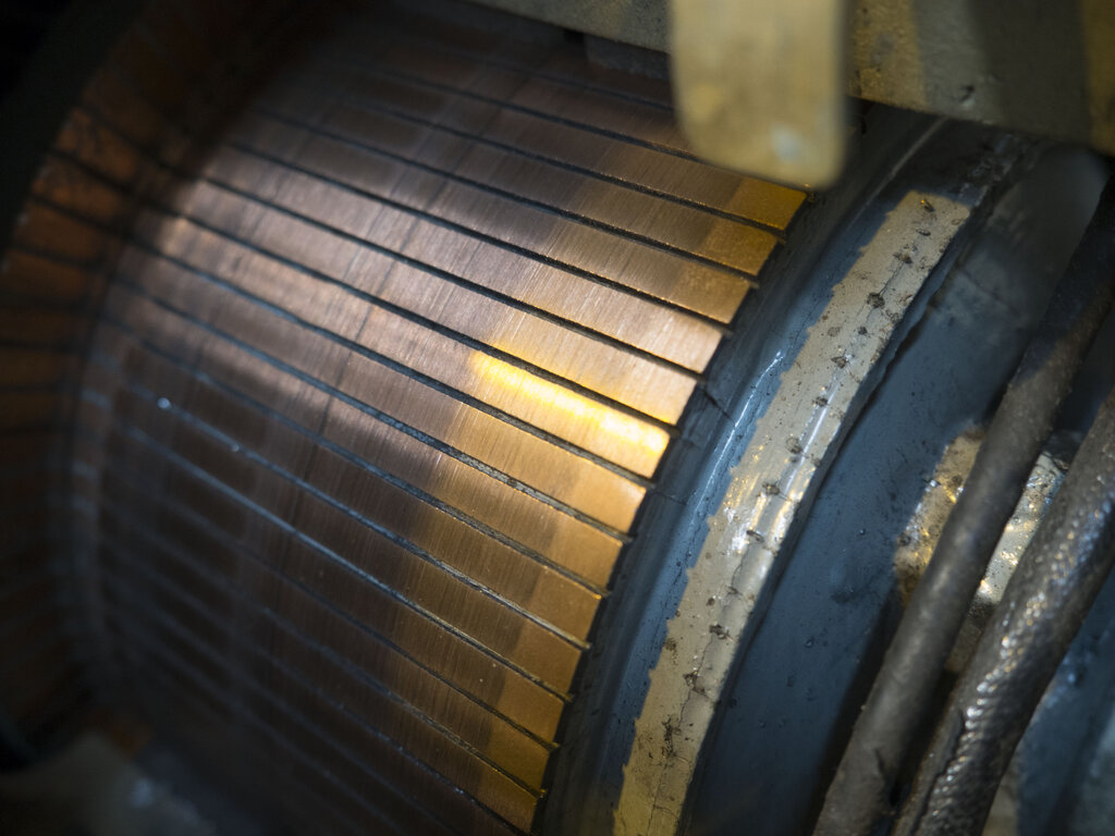
Whether on slip rings or a commutator, the brush gear assembly is critical. The brushes are typically made of a carbon-graphite composite, which is conductive yet soft enough not to damage the rings. Each brush is held in a holder and pressed against the rotating surface by a calibrated spring. Correct spring tension is vital. Too little, and the electrical connection will arc and fail; too much, and the brushes and rings will wear out prematurely. This is a common inspection point under [{
Housing and Support
Finally, the entire assembly is enclosed in a sturdy housing, usually made of aluminum alloy. This case has two main parts: the drive end frame and the commutator (or slip ring) end frame. These frames contain the high-precision bearings that support the rotor shaft, allowing it to spin freely with minimal friction.
The housing serves several purposes. It provides rigid mounting points to attach the generator to the engine's accessory drive pad. It protects the delicate internal components from the harsh engine environment. And it often includes integrated cooling fins or a fan attached to the rotor shaft to dissipate the significant heat generated during operation.
Ready to test your knowledge of generator construction?
What is the primary reason for constructing the stator and rotor cores from thin, insulated laminations?
In a typical three-phase aircraft alternator, what is the spatial displacement between the separate sets of stator windings?
Understanding these mechanical details is the first step toward diagnosing and maintaining aircraft electrical systems effectively.