Understanding PCB Schematics
Introduction to Schematic Diagrams
The Language of Circuits
Imagine trying to build a complex piece of furniture using only a photograph of the finished product. You could guess at the dimensions and figure out where the screws go, but it would be a frustrating process full of trial and error. A much better approach is to use a blueprint, which shows exactly how each piece connects to the others.
In electronics, a schematic diagram is that blueprint. It’s a drawing that illustrates how the components of an electronic circuit are connected.
schematic
noun
A diagram that represents the elements of a system using abstract, graphic symbols rather than realistic pictures.
Schematics don't show what a circuit looks like physically. Instead, they focus on its function. They use a universal language of symbols to represent different electronic components and lines to show the connections between them. This clarity is their superpower. Anyone who understands the language can look at a schematic and know exactly how the circuit is supposed to work, regardless of how the parts are physically arranged.
A schematic is how we describe the connectivity, and the types of devices in an analog circuit.
Blueprint vs. Building
It's crucial to understand the difference between a schematic and a physical layout, like a Printed Circuit Board (PCB). A schematic tells you what is connected, while a physical layout shows you where the components are actually placed and how the wires are routed.
Think of it like a subway map. The schematic is the simplified map you see in the train car, showing the stations and the lines connecting them. It’s designed for clarity, so you can easily plan your route from one station to another. The physical layout, on the other hand, is like a satellite view of the city, showing the actual, winding paths the subway tunnels take underground. Both are useful, but they serve very different purposes.
A schematic prioritizes logical connections. This abstraction makes it much easier to analyze how a circuit works and to troubleshoot problems. A physical layout, on the other hand, deals with real-world constraints like component size, heat dissipation, and minimizing electrical interference.
A Universal Language
For schematics to be useful, everyone needs to agree on what the symbols mean. Imagine if road signs were different in every city! It would be chaos. The same is true for electronics. Standardized symbols ensure that an engineer in Japan can understand a schematic drawn by a hobbyist in Brazil.
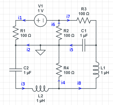
These symbols are simple graphical representations of electronic components. While there are hundreds of them, most circuits use a handful of common ones.
| Component | Symbol | Function |
|---|---|---|
| Resistor |  | Limits the flow of current. |
| Capacitor |  | Stores and releases electrical energy. |
| LED (Light Emitting Diode) |  | Emits light when current flows through it. |
| DC Voltage Source |  | Provides a constant voltage (like a battery). |
Learning to read schematics is like learning the grammar of electronics. Once you know the rules, you can understand and build almost anything.
By using these standard symbols, schematics provide a clear, concise, and universal way to document an electronic circuit's design. This makes collaboration, manufacturing, and repair vastly more efficient.
Ready to check your understanding?
What is the primary purpose of an electronic schematic?
A schematic diagram is most analogous to which of the following?
Understanding schematics is the first step toward designing, building, and troubleshooting your own electronic projects.