Specialized Network Engineering
Advanced Enterprise Switching
Smarter Loop Prevention
In any large network, redundant links between switches are essential for uptime. But this redundancy creates a problem: Layer 2 loops. Without a control mechanism, a single broadcast frame could circle forever, creating a broadcast storm that grinds the network to a halt.
The classic solution is the Spanning Tree Protocol (STP), which logically blocks redundant paths to create a loop-free topology. While effective, the original STP is slow. It can take 30 to 50 seconds to recover from a link failure, an eternity in a modern enterprise. This recovery time is known as convergence—the time it takes for all switches to agree on a new, stable topology after a change. Faster protocols were needed.
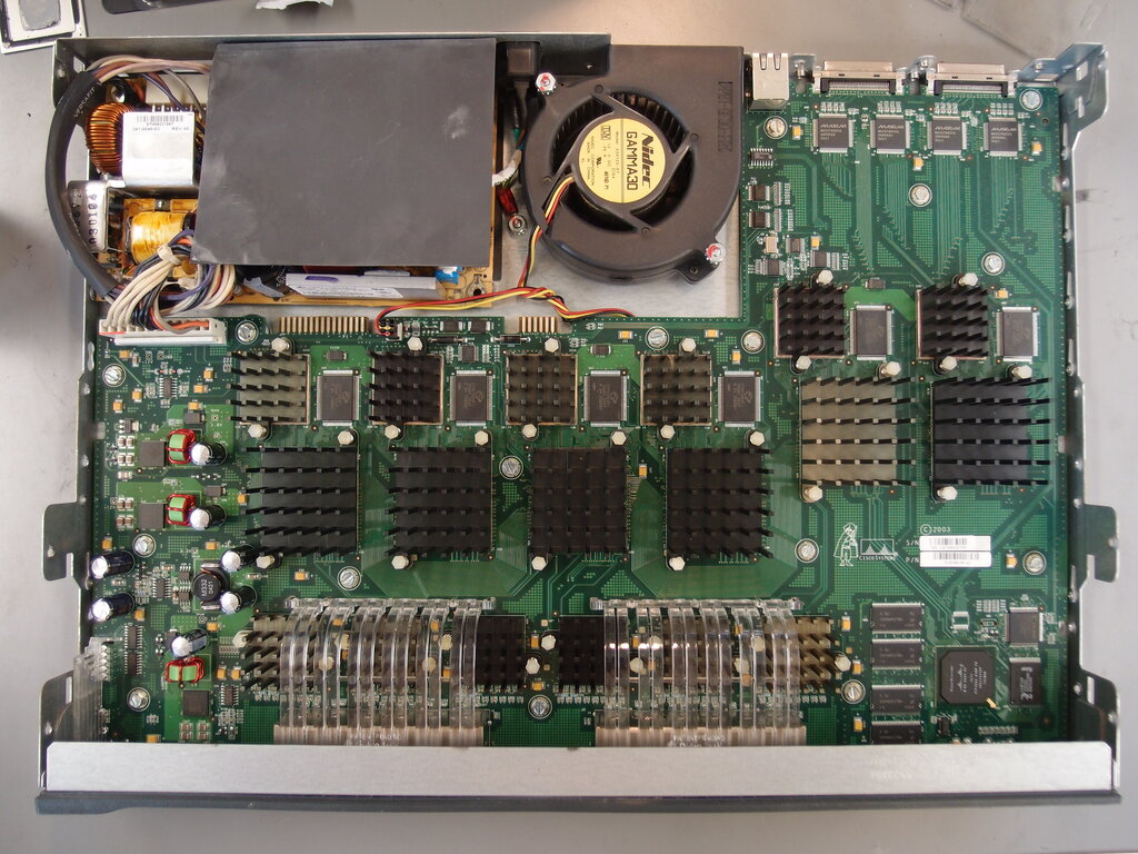
Rapid Spanning Tree Protocol (RSTP), or IEEE 802.1w, is the successor. It drastically cuts convergence time, often to just a few seconds or even milliseconds. It achieves this by actively negotiating with neighboring switches and simplifying port states. Instead of the five states in classic STP, RSTP uses three: Discarding, Learning, and Forwarding. This allows a backup port to switch to forwarding almost instantly if the primary path fails.
For even greater efficiency, we have Multiple Spanning Tree Protocol (MSTP), or IEEE 802.1s. MSTP allows you to create multiple, independent spanning tree instances and assign different VLANs to each. This is a powerful form of load balancing. For example, you can configure one set of VLANs (Instance 1) to use one physical link, and another set (Instance 2) to use a redundant link. Both links are actively forwarding traffic, just for different VLANs, eliminating the waste of blocked ports common in STP and RSTP.
| Feature | STP (802.1D) | RSTP (802.1w) | MSTP (802.1s) |
|---|---|---|---|
| Convergence Time | 30-50 seconds | 1-10 seconds | 1-10 seconds |
| Port States | 5 (Disabled, Blocking, Listening, Learning, Forwarding) | 3 (Discarding, Learning, Forwarding) | 3 (Discarding, Learning, Forwarding) |
| Load Balancing | No (1 tree for all VLANs) | No (1 tree for all VLANs) | Yes (Multiple instances for VLAN groups) |
| Standard | Obsolete | Industry Standard | For complex multi-VLAN environments |
Controlling the Spanning Tree
Every spanning tree has a 'root bridge'—a switch that serves as the central reference point for the entire topology. All other switches calculate their best path to this root. The root bridge is elected based on the lowest Bridge ID, a value combining a configurable priority number and the switch's MAC address.
If you don't manually configure the priority, the switch with the lowest MAC address wins. This is risky. An old, underpowered access switch in a closet could accidentally become the root, forcing traffic from your high-performance core to take a bizarre, inefficient path across the network. This can create bottlenecks and degrade performance significantly.
Best practice is to deliberately choose your root bridge. You do this by setting a very low priority value on your most powerful, centrally located core or distribution switch. You should also configure a secondary root bridge with the next-lowest priority to take over if the primary fails.
Always set the root bridge priority manually. A predictable traffic path is a stable traffic path.
Bundling Links for Speed and Safety
A single link between two critical switches is both a bandwidth bottleneck and a single point of failure. The solution is to bundle multiple physical links into a single logical channel. This is called link aggregation, most commonly implemented as EtherChannel on Cisco devices.
To create an EtherChannel, you can't just plug in multiple cables; the switches need to negotiate the bundle. The industry standard for this is the Link Aggregation Control Protocol (LACP), defined in IEEE 802.3ad. LACP allows switches to automatically form a channel, verify link integrity, and add or remove links from the bundle if they fail or recover. This provides both increased bandwidth and seamless redundancy.
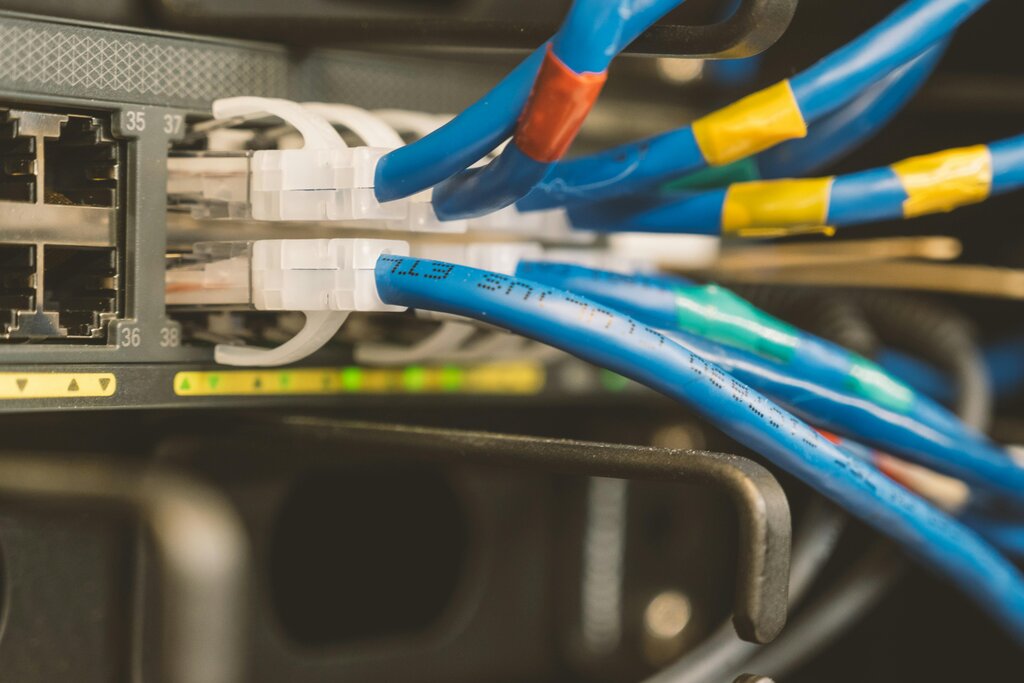
When traffic is sent over an EtherChannel, it must be distributed across the physical links in the bundle. A switch can't just send one packet down link 1, the next down link 2, as this could cause frames to arrive out of order. Instead, the switch uses a load-balancing algorithm to decide which link to use for each traffic flow. This algorithm hashes values from the packet headers—like the source MAC address, destination IP, or a combination of both—to consistently assign a specific flow to a specific physical link. For example, using a 'source-dest-ip' hash means all traffic between the same two IP addresses will always travel over the same physical link, preserving order while distributing different conversations across the other links.
The Access Layer Dilemma
One of the biggest design decisions in a campus network is where to stop Layer 2 and start Layer 3. Do you extend VLANs all the way to the user's desk ('Layer 2 at the Edge'), or do you make every access switch its own routed segment ('Layer 3 to the Access')?
Layer 2 to the Access Layer This traditional model involves creating large VLANs that span multiple access switches, all connected back to a central distribution switch that handles the routing between VLANs. This design is simple to manage and allows for easy device mobility—a user can move their laptop from one side of the building to another and stay on the same IP subnet. However, it creates a very large broadcast domain. A broadcast storm or a spanning-tree issue on one switch can potentially impact hundreds or thousands of users.
Layer 3 to the Access Layer In this modern design, also called a 'routed access' model, routing is pushed down to the access switch. Each access switch is its own small, self-contained Layer 3 segment. This dramatically shrinks broadcast domains, containing any potential issues to a single switch. It also makes better use of redundant uplinks, as routing protocols like OSPF can use multiple paths simultaneously (Equal-Cost Multi-Path, or ECMP). Spanning tree is still run, but its domain is so small that it becomes almost irrelevant.
The trade-off is complexity and the loss of seamless mobility. If a user moves to a different access switch, their device must get a new IP address. For most modern use cases, especially with the prevalence of wireless, this is no longer a significant issue.
A final aspect of managing a switched network is keeping things tidy. When you have dozens of switches and hundreds of VLANs, you don't want to send traffic for every single VLAN over every trunk link. If an access switch only has devices in VLANs 10 and 20, there's no need for it to receive broadcast traffic from VLAN 30. VLAN pruning is the process of automatically or manually preventing unnecessary VLAN traffic from crossing trunk links.
While Cisco's proprietary VLAN Trunking Protocol (VTP) can automate this, it comes with its own risks. A misconfiguration on one VTP server can wipe out the VLAN database on every switch in the domain. For this reason, many network engineers prefer to run VTP in transparent mode, where each switch's VLAN database is managed locally, and use manual trunk pruning for maximum control and stability.
What is the primary advantage of Rapid Spanning Tree Protocol (RSTP) compared to the original Spanning Tree Protocol (STP)?
To ensure a powerful, centrally located switch becomes the root bridge, a network administrator should configure it with the lowest __________.
These advanced switching concepts are the building blocks of a modern, resilient, and high-performance enterprise network. Mastering them allows you to move beyond basic setups and engineer infrastructure that can scale effectively and recover from failures in seconds.