Solar System Single Line Diagram Design
Introduction to Single-Line Diagrams
Simplifying Complexity
Electrical systems, especially large ones, are incredibly complex. They often involve three separate circuits working together, a setup known as a three-phase system. Trying to draw every single wire and connection for such a system would result in a diagram that’s cluttered and difficult to read.
This is where the single-line diagram (SLD) comes in. Think of it like a subway map. A subway map doesn't show every street, building, and tree in a city. It shows the essential information: the train lines, the stations, and how they connect. An SLD does the same for an electrical system. It uses a single line to represent the path of power flow, even in a three-phase system, making it much easier to understand the overall layout.
A single-line diagram is a simplified, symbolic representation of an electrical system, showing the main components and their connections.
Engineers use SLDs for almost every stage of a project. During the design phase, it's a blueprint for the entire system. For analysis, it helps in calculating how the system will behave under different conditions. And for maintenance, it's an indispensable guide for troubleshooting problems safely.
The Language of Diagrams
To read an SLD, you need to know its language, which consists of standard symbols. These symbols are like a universal alphabet for electrical engineers, allowing them to understand diagrams from anywhere in the world. Each symbol represents a specific component, from the source of the power to the equipment that uses it.
| Component | Symbol Description | Function |
|---|---|---|
| Generator | A circle with a 'G' or '~' inside | Produces electrical power. |
| Transformer | Two interlocking circles or coils | Changes voltage levels up or down. |
| Circuit Breaker | A square with a diagonal line | A switch that automatically trips to protect the circuit from overloads. |
| Busbar | A thick, straight line | A conductor that connects multiple circuits together. |
| Load | An arrow pointing away from a busbar | Represents the equipment that consumes electricity. |
By combining these symbols, an SLD can provide a clear picture of how power is generated, transformed, and distributed. The diagram also includes important ratings and specifications, like voltage levels and power ratings, giving a complete overview of the system's characteristics.
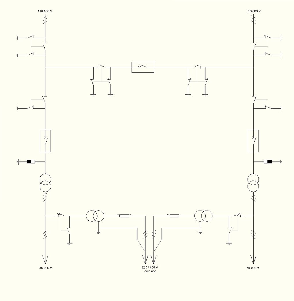
Putting It All Together
Every SLD tells a story about the flow of power. It starts at the power source, which could be a large generator or a connection to the main utility grid. From there, the diagram shows the path electricity takes.
The power often goes to a busbar, which acts like a central distribution hub. Connected to the busbar are various components. Transformers might step the voltage up for long-distance transmission or step it down for local use. Circuit breakers are placed at key points to protect equipment and ensure safety by interrupting the flow of power if a fault occurs. Finally, the lines lead to the loads, which are the ultimate destinations for the electricity.
In short, an SLD is the essential roadmap for any electrical system. It provides a high-level view that is critical for safe design, efficient operation, and effective troubleshooting.
Now, let's review what you've learned about these fundamental diagrams.
What is the primary purpose of a Single-Line Diagram (SLD) in representing a complex three-phase electrical system?
A Single-Line Diagram is often compared to a _______ because it shows the essential connections and flow without showing every minor detail.
Understanding SLDs is the first step in being able to analyze and design any complex electrical system, including solar power installations.