Professional Path to Silicon Architecture
HDL and RTL Modelling
From Gates to Code
You understand how logic gates like AND, OR, and NOT form the building blocks of digital circuits. But how do we design a modern processor with billions of these gates? Drawing them by hand is impossible. Instead, we describe hardware using a special type of programming language.
This is where (HDLs) come in. Think of an HDL not as a set of instructions for a computer to execute one-by-one, but as a blueprint for a physical circuit. When you write HDL code, you're defining how gates and wires should be connected to perform a specific function.
Verilog is a hardware description language (HDL) used to design and model electronic systems, especially digital circuits.
The dominant languages today are Verilog and its more powerful successor, SystemVerilog. While VHDL is also used, we'll focus on the Verilog family due to its widespread adoption in the industry. SystemVerilog is a superset of Verilog, meaning any valid Verilog code is also valid SystemVerilog. It adds features that make designing and, crucially, verifying large, complex chips much easier.
| Feature | Verilog | SystemVerilog |
|---|---|---|
| Primary Use | Hardware design and simple verification | Complex hardware design and advanced verification |
| Data Types | Basic (reg, wire) | Richer types (logic, structs, enums) |
| Syntax | C-like | Superset of Verilog, with C++ and Java features |
| Verification | Rudimentary tasks | Powerful, object-oriented features (classes, constraints) |
Register Transfer Level
We don't use HDLs to describe individual logic gates. That would still be too tedious. Instead, we design at a higher level of abstraction called Register Transfer Level (RTL). RTL modelling focuses on the flow of data between registers, which are small, temporary storage elements, and the logical operations performed on that data.
This approach lets us describe the behaviour of a circuit, like an Arithmetic Logic Unit (ALU), without getting bogged down in the gate-level details. A special tool called a synthesis tool then reads our RTL code and automatically converts it into a netlist of logic gates.
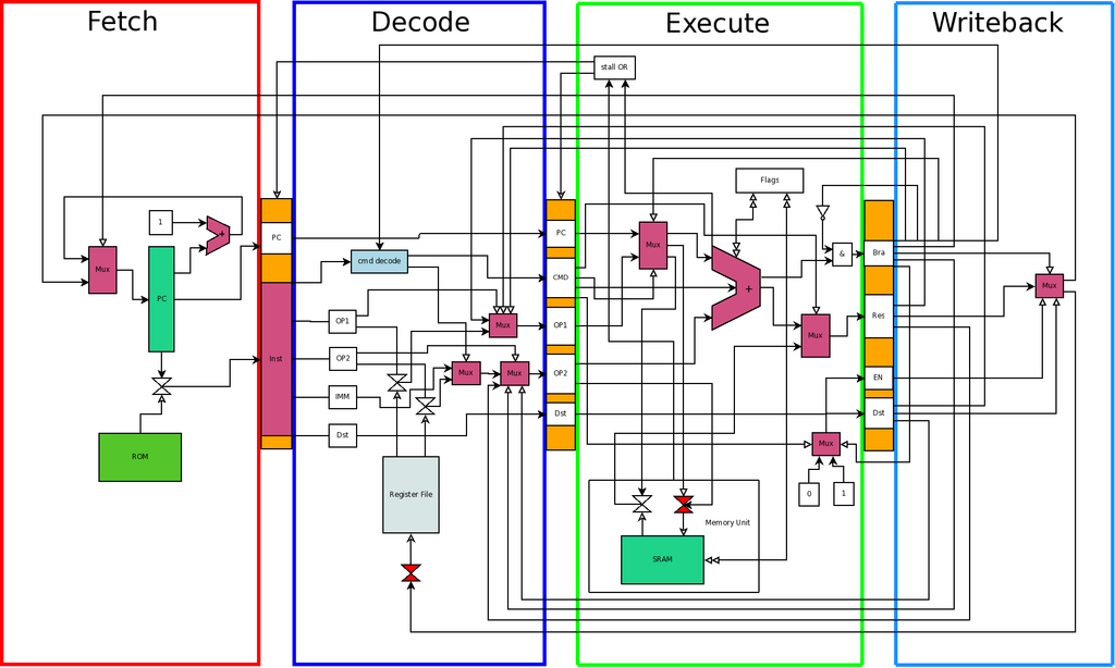
A critical concept in RTL is synthesis. Not all HDL code can be turned into a physical circuit. Synthesisable code describes hardware that can actually be built, like logic gates and flip-flops. Non-synthesisable code is used only for simulation and verification, to create testbenches that check if our design works correctly. For example, timing delays like #10 are ignored by synthesis tools because you can't create a gate with a guaranteed 10-nanosecond delay. The actual delay depends on the physical layout and manufacturing process.
Coding for Hardware
Writing RTL requires a different mindset than software programming. Two of the most important concepts are blocking and non-blocking assignments.
In Verilog, a blocking assignment (=) is executed sequentially. The next line of code doesn't run until the current one is finished. A non-blocking assignment (<=) schedules an update to happen at the end of the current time step. All right-hand sides are evaluated first, and then all left-hand sides are updated simultaneously.
This distinction is vital for describing hardware correctly. Use blocking assignments for combinational logic (where outputs depend only on current inputs). Use non-blocking assignments for sequential logic (where outputs depend on a clock signal), like registers.
// A simple D-type flip-flop (a basic register)
// This describes sequential logic, so we use non-blocking assignments.
module d_ff (
  input wire clk,
  input wire d,
  output reg q
);

  always @(posedge clk) begin
    q <= d; // On the rising edge of the clock, q gets the value of d.
  end

endmodule
This simple always block describes a circuit that, on every positive edge of the clock signal, captures the value from input d and stores it in output q. This is the fundamental building block of memory in digital circuits.
Controlling the Flow
One of the most common and powerful constructs built with RTL is the (FSM). An FSM is a model of computation that can be in one of a limited number of states. It moves from one state to another based on its current state and external inputs. Think of a traffic light system: its states are 'Green', 'Yellow', and 'Red', and it transitions between them based on a timer.
In hardware, FSMs are used to control complex sequences of operations. For example, a memory controller uses an FSM to manage the steps of reading from or writing to RAM. A CPU's control unit is a highly complex FSM that decodes instructions and orchestrates the rest of the processor.
Finally, all RTL design is a trade-off between Power, Performance, and Area (PPA). A faster circuit (high performance) might consume more power and take up more silicon area. A smaller circuit (low area) might be slower. Good RTL coding practices, like minimizing logic levels between registers and using efficient FSM encodings, are crucial for creating designs that meet their PPA targets.
What is the primary purpose of a Hardware Description Language (HDL) like Verilog?
Register Transfer Level (RTL) design focuses on...