Professional Electrical Systems Drafting
Industrial Standards Comparison
Two Worlds of Symbols
Electrical schematics are a universal language, but like any language, they have different dialects. In the world of industrial automation and power systems, the two dominant dialects are IEC 60617, used internationally, and ANSI/IEEE 315, the standard in North America. They both describe the same components and circuits, but their visual philosophies are fundamentally different.
IEC 60617 follows a 'Box Logic' or functional approach. It uses simple, standardized geometric shapes, primarily rectangles, to represent the function of a component. The goal is clarity and simplicity; what the device does is more important than what it looks like. A box might represent a complex relay, with letters inside defining its specific function. This makes diagrams clean and easy to draw, but requires you to know what the symbols mean.
On the other hand, ANSI/IEEE 315 uses a 'Pictorial Logic.' Its symbols often try to resemble the physical component they represent. A switch symbol looks like a physical switch, and a relay symbol might show a simplified view of its internal coil and contacts. This can make diagrams more intuitive for someone familiar with the hardware, but can also lead to more complex and cluttered drawings.
Decoding a Drawing
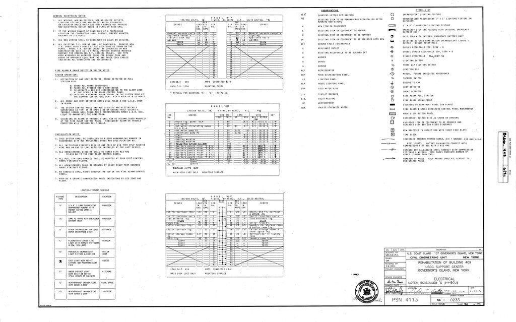
So how do you know which standard you're looking at? The answer is almost always in the drawing's title block and legend. The title block, usually in the bottom-right corner, contains metadata about the drawing: who drew it, the project name, and often, the governing standards used. It might explicitly state "Symbols per ANSI/IEEE 315" or reference a European standard like EN 60617, which is the European version of the IEC standard.
The legend is your dictionary for the schematic. It provides a list of symbols used in the drawing and what they represent. By checking the legend for a few key components, like a circuit breaker or a relay, you can quickly identify the standard. Keep an eye out for references to other regional standards that are often based on IEC, such as BS (British Standard) or DIN (German Institute for Standardization).
Let's look at a few common industrial components to see the difference in practice. A contactor is a heavy-duty relay used for switching high-power loads like motors.
Under IEC 60617, a contactor's main power contacts are shown as a simple rectangle, often with numbers indicating the terminals. In an ANSI/IEEE 315 diagram, you'll see a symbol that looks more like a traditional switch, but larger or bolder to signify its power-handling capability. The coil that activates the contactor is drawn separately in both standards, but again, the ANSI symbol for a coil (a series of loops) is more pictorial than the IEC rectangle.
Circuit breakers and protection relays show a similar divide. The IEC circuit breaker is a box with an arc symbol inside. The ANSI version shows a switch contact with a curved line indicating the thermal overload trip mechanism. An ANSI protection relay is a circle, while its IEC counterpart is a box, often with a specific letter code or symbol inside to denote its function (e.g., overcurrent, differential).
Always use standardized symbols for components to ensure that your schematics are universally understood.
Understanding these two symbolic languages is crucial for anyone working with international equipment. A machine designed in Germany (using IEC) but installed in the United States (using ANSI) will have documentation that needs to be correctly interpreted by local technicians. Being fluent in both standards prevents misinterpretation, speeds up troubleshooting, and ensures safety.
Time to review what you've learned about these competing standards.
Now, let's test your ability to apply this knowledge.
What is the core philosophical difference between the IEC 60617 and ANSI/IEEE 315 schematic standards?
You are looking at an unfamiliar electrical schematic. Where are the two most reliable places on the drawing to identify which standard (like IEC or ANSI) was used?
By learning to spot the differences and knowing where to look for clues, you can confidently navigate any professional schematic, no matter where in the world it was created.