Mobile Network Call Architecture
Cellular Radio Principles
The Cellular Concept
Mobile networks solve a fundamental problem: how to serve millions of users with a limited slice of the radio spectrum. The solution is to divide a large service area into smaller zones called cells. Each cell contains a base station that provides coverage to the mobile phones, or User Equipment (UE), within its boundary. This cellular structure is the key to efficient spectrum use.
While a cell's actual radio coverage is an irregular shape influenced by terrain and buildings, network planners model them as hexagons. Why hexagons? They are the geometric shape that best approximates a circle while allowing for perfect tessellation. This means they can fit together to cover an entire area without any gaps or overlaps, unlike circles.
Frequency Reuse
The real magic of the cellular model is , the practice of using the same set of radio frequencies in different geographic areas. A block of spectrum is divided into smaller sets of channels. A group of adjacent cells, called a cluster, is then assigned the complete set of channels, with each cell using a different subset.
Once a cluster is established, the entire frequency pattern can be repeated in adjacent clusters. The key is to separate cells using the same frequency set (co-channel cells) by enough distance to keep interference at an acceptable level. The number of cells in a cluster, N, is called the reuse factor. Common values for N are 3, 4, 7, and 12. A smaller N means more capacity, as frequencies are reused more aggressively, but it also means higher potential for interference.
The geometry of the hexagonal grid dictates the possible values for the reuse factor, N. It can be calculated using two non-negative integers, and , which represent shifts along two of the hexagonal grid axes to find the next nearest co-channel cell.
The Air Interface
The radio link between the user's phone (UE) and the cell tower is known as the air interface. Each cell is served by at least one fixed-location transceiver called a Base Transceiver Station (BTS). The BTS houses the radio antennas, amplifiers, and processing hardware that manage the communication for all UEs in its cell.
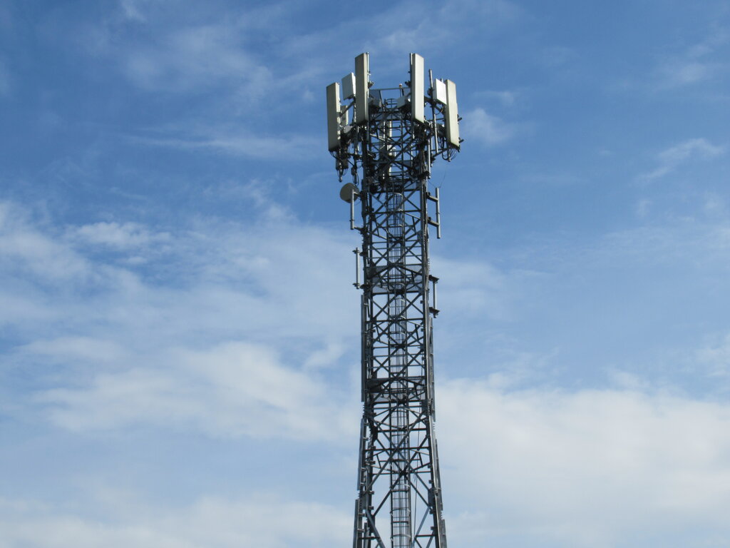
The quality of this radio link is not constant. As a radio signal travels from the BTS to the UE, its strength decreases with distance. This effect is called path loss. The signal can also be blocked or reflected by obstacles like buildings, hills, and even foliage, a phenomenon known as shadowing. These factors create significant challenges for maintaining a reliable connection.
Network engineers perform a calculation called a link budget to ensure the signal received at either end of the link is strong enough for reliable communication. This involves summing all the gains (like transmitter power and antenna gain) and subtracting all the losses (like path loss and cable losses) in the system.
Another major challenge is co-channel interference. This occurs when a UE receives weak but unwanted signals from distant base stations that are using the same frequency channels. The goal of network design is to maximise the Signal-to-Interference Ratio (SIR), ensuring the desired signal is much stronger than the combined noise from all interfering cells. The choice of the reuse factor, N, is a direct trade-off between network capacity and managing this interference.
Let's test your understanding of these core principles.
What is the primary reason mobile networks divide a large service area into smaller zones called "cells"?
Why do network planners typically model cells as hexagons instead of circles or squares?
Understanding how cellular networks manage a finite resource like radio spectrum is the first step to mastering mobile communication. By dividing space into cells and carefully reusing frequencies, a network can serve a massive number of users simultaneously.