Mathematics for Computer Engineering Excellence
Propositional Logic Design
From Statements to Circuits
At the heart of every computer is a system of logic, translating complex instructions into simple true or false signals. Propositional logic is the formal language we use to do this. It lets us take statements about the world and represent them with symbols, which can then be manipulated and ultimately turned into physical circuits.
We start with basic propositions, which are declarative sentences that can be either true or false. For example, "The switch is on" is a proposition. In logic, we represent these with variables like , , and . This abstraction allows us to focus purely on the logical structure of an argument or a circuit, regardless of what the propositions actually mean.
Logical Connectives
Propositions are rarely useful on their own. We combine them using logical connectives, which act as the grammar of our logical language. Each connective has a direct counterpart in digital hardware: a logic gate.
Connective
noun
A symbol or word used to connect two or more sentences or propositions.
Let's look at the fundamental connectives and their corresponding truth tables, which show the output for every possible combination of inputs.
| Connective | Symbol | English | Gate | Truth Table (p, q → Output) |
|---|---|---|---|---|
| Negation | NOT | NOT | T→F, F→T | |
| Conjunction | AND | AND | TT→T, TF→F, FT→F, FF→F | |
| Disjunction | OR | OR | TT→T, TF→T, FT→T, FF→F | |
| Exclusive Or | XOR | XOR | TT→F, TF→T, FT→T, FF→F |
Each of these logical operations is performed by a physical device called a logic gate. The rules defined in the truth tables are built directly into the electronics.
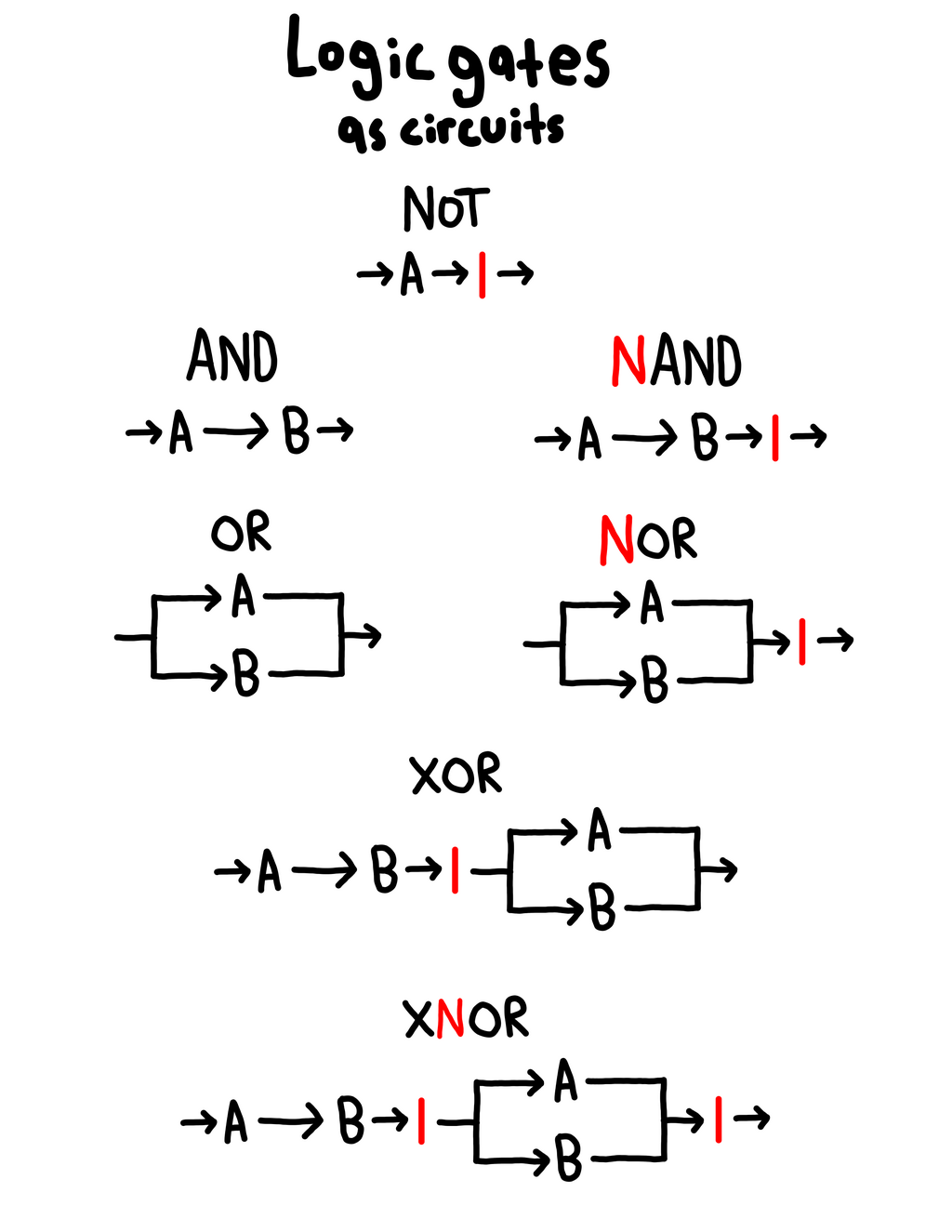
Simplifying with Equivalences
When designing circuits, complexity costs money, space, and speed. A simpler logical expression translates to a circuit with fewer gates. Logical equivalences are rules that allow us to rewrite a formula into a different, simpler form without changing its overall meaning or truth value. Two expressions are equivalent if they have identical truth tables.
The goal is to find the most efficient logical expression before building the physical circuit. One of the most powerful tools for this is a pair of rules known as De Morgan's Laws.
These laws are incredibly useful in circuit design. For example, a NAND gate () is functionally equivalent to an OR gate with inverted inputs. This gives engineers flexibility to build circuits using fewer types of gates, which can simplify manufacturing.
Other key equivalences include the distributive laws, which work just like in algebra:
Conditional Logic
Conditional statements are the foundation of decision-making in programs and circuits. They represent "if-then" scenarios.
| Connective | Symbol | English | Truth Table (p, q → Output) |
|---|---|---|---|
| Conditional | if , then | TT→T, TF→F, FT→T, FF→T | |
| Biconditional | if and only if | TT→T, TF→F, FT→F, FF→T |
The conditional statement is only false when a true premise () leads to a false conclusion (). In all other cases, the promise of the statement is upheld.
The biconditional, , is true only when and have the same truth value. It's equivalent to , and it's the logic behind the XNOR (Exclusive NOR) gate.
Since hardware doesn't typically include a dedicated "implication gate," we build conditionals from simpler gates. The conditional is logically equivalent to . This simple equivalence is fundamental to implementing decision logic in hardware.
Translating Logic to Gates
The final step is to translate a complete propositional formula into a gate-level diagram. This process turns an abstract mathematical statement into a blueprint for a physical circuit. Each variable becomes an input wire, and each logical connective becomes its corresponding gate.
Let's take the expression . We can build this circuit step-by-step:
- Start with inputs for , , and .
- Use a NOT gate to get .
- Feed and into an AND gate.
- Take the output of the AND gate and the input and feed them into an OR gate.
The final output of the OR gate represents the truth value of the entire expression.
This direct translation from logic to hardware is the foundation of digital design. By mastering propositional logic, you understand the fundamental principles that govern how every digital device thinks.
Ready to test your understanding? Let's try a few questions.
In propositional logic, what is the primary characteristic of a proposition?
Why are logical equivalences crucial in the design of digital circuits?
Understanding these formal structures allows us to move from abstract logic to concrete, functional hardware, which is the core challenge of computer engineering.