Mastering Two-Port Network Parameters
Port Fundamentals and Z-Parameters
The Black Box Approach
In circuit analysis, we often encounter complex networks of components. Instead of analyzing every resistor, capacitor, and inductor inside, we can treat the entire network as a single unit with a set of terminals for input and output. This simplifies things greatly.
A two-port network is a common way to model these systems. It's an electrical network with two pairs of terminals, forming two ports: an input port and an output port. We treat what's inside the network as a "black box." We don't need to know its internal structure, only how the voltages and currents at the ports relate to each other.
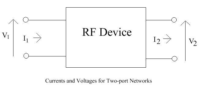
We define four key variables:
- : Voltage at the input port (Port 1)
- : Current entering the input port
- : Voltage at the output port (Port 2)
- : Current entering the output port
By convention, currents and are defined as flowing into the network. The goal is to find a set of equations that describe the behavior of this black box using only these four external variables.
Defining Z-Parameters
One of the most direct ways to characterize a two-port network is by expressing the port voltages (, ) as functions of the port currents (, ). This relationship is defined by a set of constants called impedance parameters, or Z-parameters.
These linear equations show that the voltage at each port is a combination of the effects of the currents at both ports. The terms tell us the strength of these relationships. We can also write this relationship more compactly using matrix notation.
Finding the Parameters
To find the value of each Z-parameter, we can cleverly simplify the defining equations by setting one of the currents to zero. Setting a current to zero is the same as creating an open circuit at that port.
Let's find and by making the output port an open circuit ().
When , our two main equations become:
From here, we can solve for and .
Now, let's find and by making the input port an open circuit ().
This time, our equations simplify to:
Solving gives us the remaining parameters.
By making two simple measurements (one with the output open, one with the input open), we can fully characterize the linear behavior of our black box.
The T-Equivalent Circuit
The Z-parameters aren't just abstract numbers; they can be used to build an equivalent circuit that behaves identically to our original black box. The most common model for Z-parameters is the T-equivalent circuit.
Let's revisit the Z-parameter equations. We can interpret them as Kirchhoff's Voltage Law (KVL) equations for two loops.
The terms and represent dependent voltage sources. They show how the current in one loop creates a voltage in the other. We can build a circuit that directly represents these equations.
This model is valid for any linear two-port network. The components in the T-circuit are expressed in terms of the Z-parameters. The dependent voltage source accounts for any non-symmetrical behavior between the input and output.
Reciprocity and Symmetry
The values of the Z-parameters can tell us important things about the internal nature of the black box.
Reciprocity A network is reciprocal if the relationship between the voltage at one port and the current at the other is the same regardless of which is the input and which is the output. In other words, if you swap the voltage source and the ammeter, you get the same reading. For passive networks made only of resistors, capacitors, and inductors, this is always true. This property is reflected in the Z-parameters.
When a network is reciprocal, the dependent voltage source in the T-equivalent circuit disappears, since . The model simplifies to just three impedance elements.
Symmetry A network is symmetrical if its input and output ports can be interchanged without changing the electrical behavior. This means the impedance looking into Port 1 (with Port 2 open) is the same as looking into Port 2 (with Port 1 open).
If a network is both reciprocal and symmetrical, then and . This greatly simplifies analysis.
Time to test your understanding of Z-parameters.
What do the Z-parameters of a two-port network fundamentally describe?
To experimentally determine the value of the parameter , what condition must be created at the ports?
By defining, measuring, and modeling with Z-parameters, we can analyze complex circuits without needing to know every detail of their construction. This black box approach is a powerful tool in electrical engineering.