Mastering RGB Lighting Systems
PWM Color Mixing
Faking Analog with Digital Pulses
Microcontrollers think in black and white: on or off, high or low. But to create a rich spectrum of colors, we need shades of gray—or more accurately, shades of red, green, and blue. Controlling the brightness of an LED isn't an on/off task; it requires a seemingly analog level of control. The trick is to use a digital signal to mimic an analog one through a technique called Pulse-Width Modulation (PWM).
Imagine flicking a light switch on and off so fast that your eyes can't keep up. Instead of seeing a flicker, you'd perceive a steady, dim light. The longer the switch stays on compared to off in each cycle, the brighter the light appears. This is the essence of PWM. A microcontroller sends a high-frequency square wave to the LED, rapidly turning it on and off thousands of times per second. By controlling the width of the 'on' pulse relative to the total cycle time, we can precisely control the perceived brightness.
Duty Cycle
noun
The percentage of time that a signal is in the 'on' or 'high' state during one complete cycle. A 100% duty cycle means the signal is always on, while a 0% duty cycle means it's always off.
This percentage is what we call the duty cycle. For color mixing, this concept is usually mapped to an 8-bit value, ranging from 0 to 255. A value of 0 corresponds to a 0% duty cycle (fully off), 255 corresponds to a 100% duty cycle (fully on), and a value like 127 is roughly a 50% duty cycle, making the LED appear at half brightness.
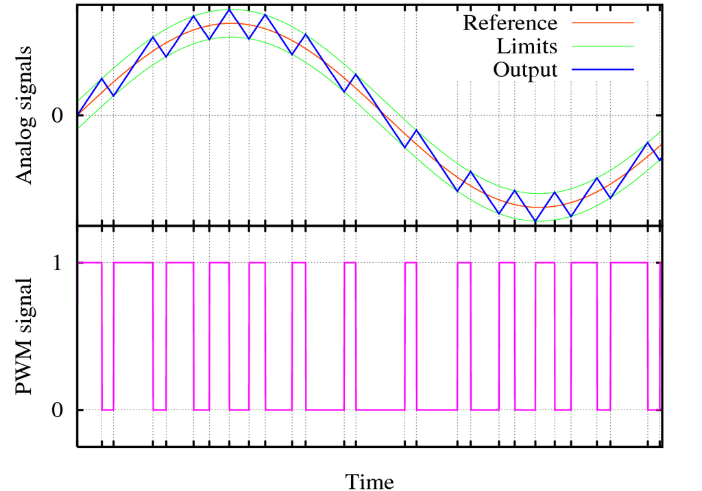
Applying this to an RGB LED is straightforward. We simply generate three independent PWM signals: one for the red channel, one for the green, and one for the blue. By setting the duty cycle for each channel, we can mix any color within the LED's gamut. For example, setting Red to 255, Green to 127, and Blue to 0 would create a bright orange color.
Hardware vs Software PWM
Generating these high-frequency pulses can be done in two ways: with dedicated hardware or through software.
Hardware PWM utilizes built-in peripherals on the microcontroller. You configure a few registers—setting the frequency and desired duty cycle—and the hardware takes over, generating a stable, precise square wave in the background. This is extremely efficient, as it requires no processing power from the CPU once it's set up. The main drawback is that a microcontroller only has a limited number of hardware PWM pins.
Software PWM, on the other hand, uses code to manually toggle a general-purpose I/O pin high and low. This can be done on any digital pin, offering great flexibility. However, it comes at a cost. The CPU is directly responsible for timing the pulses, which consumes processing cycles. If the CPU is busy with other tasks, the timing of the PWM signal can become inconsistent, leading to visible flicker or color instability. This inconsistency is often called jitter and is a major reason hardware PWM is preferred for demanding applications like motor control or high-quality lighting.
Circuit Configurations
When you buy an RGB LED, it will have four pins. Three control the individual colors, and one is a common connection. This common pin determines the LED's type and how you wire it.
A Common Cathode (CC) LED has a shared negative terminal (cathode). The common pin connects to ground (GND), and you apply a positive voltage (a high PWM signal) to the red, green, or blue pins to turn them on. This is an intuitive setup: a high signal means 'on'.
A Common Anode (CA) LED works the opposite way. It has a shared positive terminal (anode) that connects to your power source (e.g., 5V). To turn a color on, you connect its pin to ground. This means the control logic is inverted: a low signal (0% duty cycle) results in maximum brightness, and a high signal (100% duty cycle) turns the LED off.
It's crucial to know which type you have, as it dictates both your circuit design and your code. Using common cathode logic with a common anode LED will result in inverted colors, and vice versa.
Calculating Resistor Values
Each color channel in an RGB LED needs its own current-limiting resistor. This is not just to protect the LED from burning out, but also to ensure correct . The three LED dies inside the package have slightly different electrical properties, particularly their forward voltage () and ideal forward current (). You need to calculate the resistor for each channel independently.
The calculation is a direct application of Ohm's Law. For each channel, you need to know the source voltage (), the LED's forward voltage (), and your target forward current (), which is usually around 20mA (0.02A) for standard LEDs.
Example: For a red LED with on a 5V system, targeting 20mA current: .
You would repeat this calculation for the green and blue channels using their specific forward voltages. Since resistors don't come in every possible value, you'll typically choose the next standard value up from your calculated result to ensure the current stays at or below the target.
Time to check your understanding of these concepts.
What is the primary purpose of using Pulse-Width Modulation (PWM) with an LED?
A major disadvantage of software PWM compared to hardware PWM is that it can introduce timing inconsistencies, leading to flickering. This inconsistency is known as _______.
By managing duty cycles and selecting the right hardware configuration, PWM gives you precise, repeatable control over color, forming the basis for everything from simple status indicators to complex digital art installations.