Mastering Resistor Combinations in Electrical Circuits
Series Resistor Circuits
Resistors in Series
When you connect components in an electrical circuit one after another, like links in a chain, you create a series circuit. For resistors, this arrangement has a straightforward effect: their resistances add up. This single path for current flow is a key characteristic of series circuits.
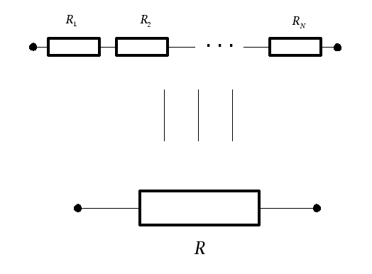
Imagine you have three resistors, , , and , connected end-to-end. The total opposition to current flow, known as the equivalent resistance (), is simply the sum of the individual resistances. This concept allows us to simplify complex circuits into a single, manageable resistor for analysis.
In a series circuit, there is only one path for the current to take. This means the current is the same through every component in the circuit.
Calculating Current and Voltage
Once you know the equivalent resistance, you can use Ohm's Law to find the total current flowing from the voltage source. If a circuit has a total voltage and an equivalent resistance , the total current is:
Because the current is constant throughout a series circuit, this is the same current that flows through , , and every other resistor in the line. So, and so on.
With the current known, you can find the voltage drop across each individual resistor. A voltage drop is the amount of voltage that is 'used up' by a component as current passes through it. Applying Ohm's Law to each resistor gives us the individual voltage drops:
- Voltage across is
- Voltage across is
- And so on for each resistor.
This leads us to an important application of (KVL). KVL states that the sum of all voltage drops across the resistors in a series circuit must equal the total voltage supplied by the source. It's a way of saying that all the voltage provided by the source must be accounted for by the components in the loop.
A Practical Example
Let's put this into practice. Consider a circuit with a 12V battery and three resistors in series: , , and .
1. Find the equivalent resistance (): Simply add the resistances together.
2. Calculate the total current (): Use Ohm's Law with the total voltage and equivalent resistance.
This means 1 Ampere of current flows through the entire circuit, including each resistor.
3. Determine the voltage drop across each resistor: Apply Ohm's Law to each resistor individually using the total current.
4. Verify with Kirchhoff's Voltage Law: The sum of the voltage drops should equal the source voltage.
The calculation checks out. This confirms our understanding of how voltage is distributed in a series circuit. Notice how the largest resistor () has the largest voltage drop.
Now, let's review these key concepts.
Ready to test your knowledge?
What is the defining characteristic of the current flowing through a simple series circuit?
If a circuit has a 10V power source and two resistors in series, and , what is the voltage drop across ?
Understanding series circuits is a fundamental step in analyzing more complex electrical systems. By combining resistors and applying these basic laws, you can simplify and solve for the behavior of any series network.