Mastering Modern Transistors
Control Mechanism Comparison
The Current vs. Voltage Debate
At the heart of modern electronics are two dominant types of transistors: the Bipolar Junction Transistor (BJT) and the Metal-Oxide-Semiconductor Field-Effect Transistor (MOSFET). While both act as amplifiers or switches, how they are controlled is fundamentally different. This distinction is the single most important factor when choosing one over the other for a specific application.
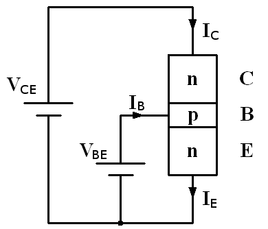
A BJT is a current-controlled device. Think of it like a faucet where the flow of water (collector current) is proportional to how much you turn a small, leaky knob (base current). A continuous flow of current into the base is required to keep the main current flowing from the collector to the emitter. This control current is small, but it is never zero while the transistor is on.
On the other hand, a MOSFET is a voltage-controlled device. The analogy here is a modern touch-sensitive faucet. You don't need a continuous force to keep it on; you just need to apply a certain pressure (voltage) to the sensor (gate). This voltage creates an electric field across an insulating layer, which then allows current to flow from the drain to the source. Once the gate is charged and the voltage is held, there is virtually no static current flow into the gate. It's the presence of the voltage, not a flow of current, that does the work.
Input Impedance and Loading Effects
This difference in control mechanism has a profound impact on a characteristic called input impedance. Because a BJT requires a continuous base current to operate, it presents a relatively low impedance to the circuit driving it. The driving circuit must be able to supply this current, which means the BJT actively draws power from the signal source. This is known as the source. If the source circuit can't provide enough current, its voltage will drop, distorting the signal it was trying to send.
A MOSFET, with its insulated gate, behaves very differently. From a DC perspective, its gate looks almost like an open circuit. It draws a tiny, often negligible, amount of leakage current. This gives it an extremely high input impedance, typically in the megaohms or even gigaohms range. Consequently, a MOSFET places a very light load on the signal source. It senses the voltage without drawing any significant current, making it ideal for interfacing with sensitive or high-impedance signal sources.
Mathematical Models
These physical differences are captured in their simplified mathematical models. The BJT is modeled as a Current-Controlled Current Source (CCCS). The output current (collector current, ) is a direct multiple of the input current (base current, ). The scaling factor is the transistor's current gain, represented by beta () or .
The MOSFET, in contrast, is modeled as a Voltage-Controlled Current Source (VCCS). The output current (drain current, ) is controlled by the input voltage (gate-source voltage, ). The key parameter here is transconductance (), which describes how effectively the gate voltage controls the drain current.
While both devices have a transconductance, it's derived differently. For a BJT, is directly proportional to the collector current (, where is the thermal voltage). This means a BJT's transconductance, and thus its gain, changes with its bias point. For a MOSFET, depends on both the bias conditions and the physical dimensions of the device, offering more design flexibility.
Understanding this core distinction, current-controlled versus voltage-controlled, is the first step in mastering transistor circuit design. It dictates everything from biasing strategies to power consumption and signal integrity.