Mastering Modern Counter Mechanisms
Synchronous Counter Foundations
The Need for Speed
In digital circuits, timing is everything. Asynchronous, or ripple, counters are simple, but they have a critical flaw: s. Each flip-flop has to wait for the one before it to change state, creating a delay that accumulates down the line. For high-frequency operations, this ripple effect can cause errors as the counter's state becomes temporarily invalid.
Synchronous counters solve this problem by ensuring every flip-flop changes state at the exact same moment.
How? By connecting every flip-flop to the same clock signal. This means all state changes are synchronized, happening precisely on the clock's edge. But this introduces a new puzzle. If every flip-flop gets the clock signal at the same time, how do we control which ones should actually toggle their state and which should stay put?
Synchronized Toggling
The answer lies not in the clock input, but in the control inputs of the flip-flops. We'll use for this, as their behavior is perfect for building counters. By feeding the output of previous stages into a chain of logic gates, we can create an "enable" signal for each subsequent flip-flop.
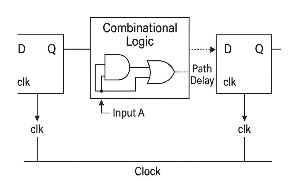
The logic follows the rules of binary counting:
- The first flip-flop (, the least significant bit) should toggle on every single clock pulse. Simple enough—we just tie its J and K inputs high.
- The second flip-flop () should only toggle when is already 1.
- The third flip-flop () should only toggle when both and are 1.
- The fourth flip-flop () toggles only when , , and are all 1.
This pattern creates a dependency on the state of all previous bits, but the decision is made with combinational logic before the next clock pulse arrives. When the clock ticks, all flip-flops that are enabled to toggle do so simultaneously.
The AND-Gate Chain
This enabling logic is built with a simple chain of AND gates. The output of the first flip-flop, , controls the J and K inputs for the second flip-flop, . For the third flip-flop, , we need to know if both and are high. We use an AND gate for that. This pattern continues for as many bits as the counter has.
The diagram shows how the output of each stage feeds into an AND gate that enables the next. enables . AND enable . AND AND enable . All toggles occur in perfect lockstep with the clock pulse, eliminating ripple delay and ensuring the counter's output is always valid immediately after a clock edge.
State Transitions
We can visualize the counter's behavior using a state transition diagram. Each circle represents a state (the binary value of the counter), and the arrows show the transition on each clock pulse. For a 4-bit synchronous up-counter, it's a simple, predictable loop through all 16 states from 0000 to 1111.
The key takeaway is that because all flip-flops see the clock at the same time and the logic is set up before the clock edge, the transition from any state to the next happens instantly and cleanly. This synchronous design is the foundation for almost all high-speed digital counting and state machine circuits found in modern electronics.
What is the primary disadvantage of asynchronous (ripple) counters that is solved by synchronous designs?
How do synchronous counters ensure that all flip-flops change state at the exact same time?