Mastering Electrical Schematic Drafting
Drafting Standards
The Universal Language of Schematics
A well-drawn schematic is like a clear sentence. It communicates a complex idea with no room for misinterpretation. While you know what individual components do, assembling them into a circuit requires a shared visual grammar. Without it, collaboration becomes impossible and expensive errors become inevitable.
This grammar is defined by drafting standards. These formal conventions ensure that any engineer, anywhere in the world, can look at a schematic and understand its function. The two most dominant standards bodies are the ANSI and the IEC.
IEC
noun
The International Electrotechnical Commission. It is a worldwide, non-profit organization that prepares and publishes international standards for all electrical, electronic, and related technologies.
ANSI, or the American National Standards Institute, is prevalent in North America, while the IEC's standards (like IEC 60617) are more common in Europe and Asia. While their symbols can differ slightly, their core principles of clarity and consistency are identical. Adhering to these standards is the first step toward professional-grade documentation.
Structuring the Drawing
Professional schematics are not free-form drawings; they are organized on a grid. This structure isn't just for neatness. Large, multi-sheet drawings use a coordinate system, much like a map, with letters along one axis and numbers along the other. This allows engineers to reference specific locations (e.g., "check the relay at C4") quickly and precisely.
Visual hierarchy is created using different line weights. A thicker line immediately draws the eye and signifies importance. For example, main power and ground lines are typically drawn with heavier lines than those carrying low-power digital signals. This simple technique helps anyone reading the schematic to quickly trace the flow of power through the system.
One of the most critical conventions governs how wires that cross are interpreted. Ambiguity here can lead to a completely non-functional or even damaged circuit. The modern standard is simple: wires are only connected if a solid dot, called a junction dot, is placed at their intersection. If two lines cross without a dot, they are not electrically connected.
This avoids the confusion of the older "hop-over" method. A four-way connection is always shown with staggered junctions to avoid a simple crossing with a dot, which can be mistaken for an accidental ink blot. This is sometimes called the 'four-way tie' rule.
Labeling for Clarity
Every single component on a schematic must have a unique identifier. This is done using reference designators—a combination of a one or two-letter code and a number. The letter indicates the type of component, while the number makes it unique. For example, R1, R2, and R3 would be the first three resistors in a design.
These letter codes are standardized, which means you can quickly identify parts even in a complex schematic. While you already know resistors are 'R' and capacitors are 'C', the system covers every type of component.
| Reference Designator | Component Type |
|---|---|
| R | Resistor |
| C | Capacitor |
| L | Inductor |
| D, CR | Diode |
| Q | Transistor |
| U, IC | Integrated Circuit |
| J | Jack / Connector |
| P | Plug |
| K | Relay |
| S, SW | Switch |
| F | Fuse |
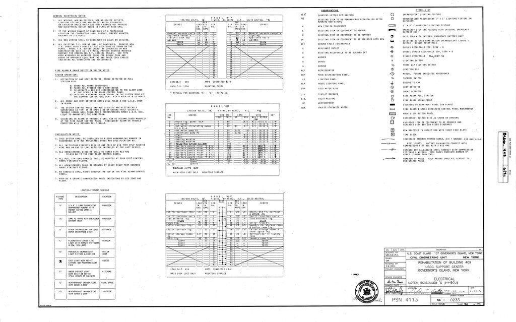
Finally, every professional schematic sheet includes a title block. This area, usually in the bottom-right corner, is the document's official record. It contains essential metadata.
A title block must contain the drawing title, the company or designer name, the sheet number (e.g., 'Sheet 2 of 5'), and a revision history. The revision block is crucial, as it tracks changes, dates, and approvals, creating a legal and technical history of the design's evolution.
By combining these standards for structure, connections, and labeling, you create documentation that is clear, professional, and universally understood. This discipline prevents ambiguity and ensures your design can be built, tested, and maintained effectively.
Which standards body's conventions for schematics are most commonly used in Europe and Asia?
According to modern schematic standards, what does it signify when two wire lines cross without a junction dot?