Mastering Balanced Three Phase Circuits
Three Phase Generation
From One Phase to Three
In a single-phase AC generator, a single coil rotating in a magnetic field produces one sinusoidal voltage. It's a simple, effective way to generate power. But to deliver more power smoothly and efficiently, we can add more coils.
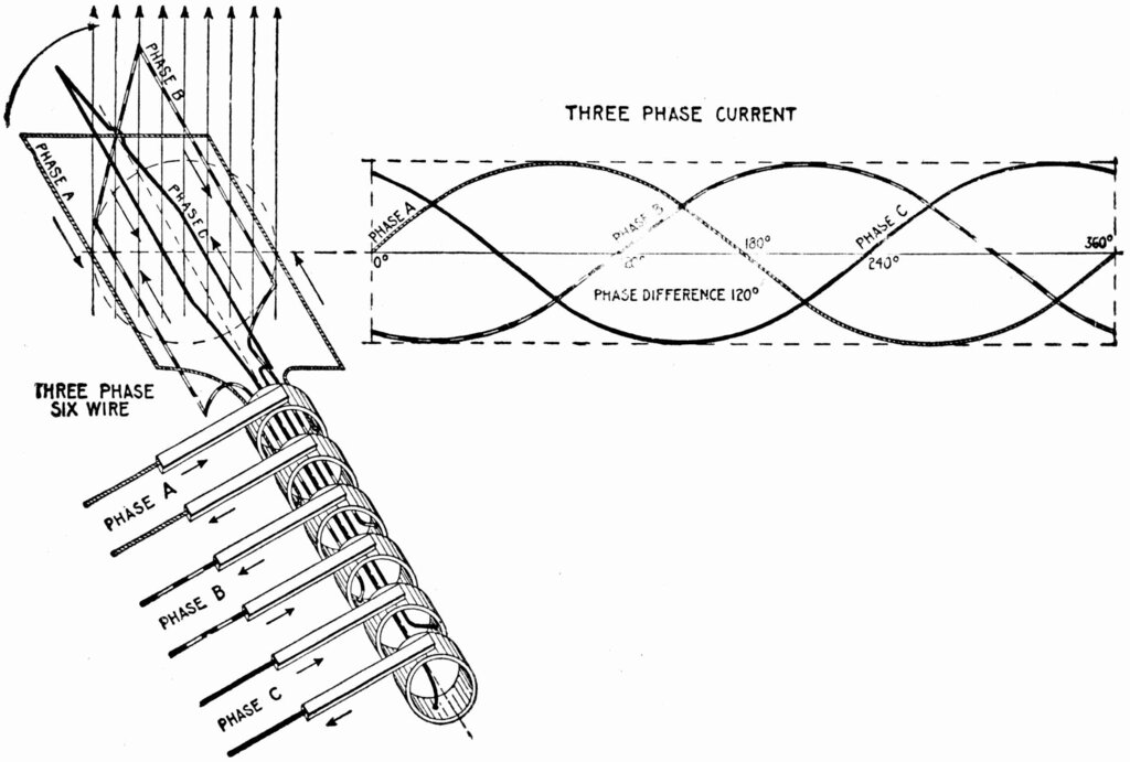
Three-phase systems use three separate coils, physically offset from each other by 120 degrees within the generator. As the rotor spins, each coil produces its own single-phase AC voltage. But because of their physical separation, the voltages they produce are also separated in time. Each voltage waveform reaches its peak 120 degrees after the previous one. This creates three distinct, predictable phases of power from a single generator.
The Math of a Balanced System
Let's assign a reference phase, which we'll call phase 'a'. We can describe its instantaneous voltage, , as a standard sine wave with a peak voltage of and an angular frequency of .
Because the second coil (phase 'b') is physically shifted by 120 degrees, its voltage waveform is identical but delayed by 120 degrees. The third coil (phase 'c') is shifted another 120 degrees, for a total of 240 degrees from our reference phase 'a'. Alternatively, we can say it leads phase 'a' by 120 degrees.
This specific order, where phase 'a' is followed by 'b', then 'c', is known as the ABC or positive sequence. If the generator's direction of rotation were reversed, the order would become ACB, or a negative sequence. The sequence is critical for applications like three-phase motors, as it determines the direction of rotation.
A key feature of a perfectly is that the instantaneous sum of the three phase voltages is always zero. At any point in time, the voltages cancel each other out.
Simplifying with Phasors
Working with these time-domain equations can be cumbersome. For steady-state AC analysis, it's much easier to convert these sinusoidal functions into —complex numbers that represent the magnitude and phase angle of a sine wave. We typically use the Root Mean Square (RMS) value for the magnitude, which is .
By convention, we set the phase angle of our reference phase 'a' to . The other phasors follow the same phase shifts we saw in the time-domain equations.
Visually, these three phasors form a symmetrical star shape, 120 degrees apart. This geometric representation makes it easy to see the balanced nature of the system.
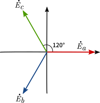
Just like with the instantaneous voltages, the vector sum of these three phasors is zero. This phasor representation is the foundation for analyzing all types of three-phase circuits and loads.