Introduction to Electronics
Electricity Basics
The Building Blocks of Electricity
At its heart, electricity is about the flow of tiny charged particles called electrons. To understand how circuits work, we need to get a handle on three fundamental ideas: current, voltage, and resistance. Think of electricity flowing through a wire like water flowing through a pipe. This analogy makes these concepts much easier to grasp.
Current
noun
The rate at which electric charge flows past a point in a circuit.
A large current means a lot of charge is moving, while a small current means very little is.
Voltage
noun
The electric potential difference between two points; the push or pressure that causes charge to move.
Without voltage, there's no push, so current won't flow. A battery or a wall outlet provides the voltage needed to run our devices.
Resistance
noun
A measure of the opposition to current flow in an electrical circuit.
Materials like copper have very low resistance, making them great for wires. Materials like rubber have very high resistance, so we use them as insulators.
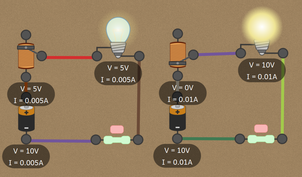
Ohm's Law
These three concepts—voltage, current, and resistance—are not independent. They are linked by a simple but powerful relationship discovered by Georg Ohm in the 1820s. Ohm's Law is the cornerstone of circuit analysis.
Ohm's Law states that the voltage across a component is directly proportional to the current flowing through it, provided the temperature and other physical conditions remain unchanged.
Mathematically, this is expressed with a clean, simple formula.
Where:
- is the voltage in volts.
- is the current in amperes.
- is the resistance in ohms.
This formula lets us calculate any one of these values if we know the other two. For example, if you have a 12-volt car battery connected to a headlight with 3 ohms of resistance, you can find the current.
So, 4 amps of current flow through the headlight. This simple calculation is used constantly in designing and troubleshooting circuits.
Putting Circuits Together
Most circuits have more than one component. The way these components are connected drastically changes how the circuit behaves. The two most basic ways to connect things are in series or in parallel.
In a series circuit, components are connected end-to-end, creating a single path for the current to flow.
Imagine old-fashioned holiday lights. If one bulb burns out, the entire string goes dark. That's because the path for the current is broken. In a series circuit, the current is the same through every component, and the total resistance is simply the sum of all individual resistances.
On the other hand, a parallel circuit provides multiple paths for the current.
In a parallel circuit, components are connected across the same two points, like the rungs of a ladder.
The wiring in your house is a parallel circuit. You can plug a lamp, a TV, and a phone charger into the same wall outlet. They all get the same voltage from the outlet, and you can turn one off without affecting the others. The total current from the outlet is the sum of the currents drawn by each device.
Understanding the difference between series and parallel connections is key to analyzing how any circuit will behave. Here's a quick summary.
| Feature | Series Circuit | Parallel Circuit |
|---|---|---|
| Current | Stays the same through all components | Splits among the branches |
| Voltage | Is divided among the components | Is the same across all components |
| Total Resistance | Increases as you add components | Decreases as you add components |
| Example | Old holiday lights | Household wiring |
Let's check your understanding of these core concepts.
In the common analogy of electricity flowing like water through a pipe, what does voltage represent?
According to Ohm's Law (), how much current flows through a circuit with a 9-volt battery and a 3-ohm resistor?
These building blocks are the foundation for everything else in electronics. Mastering them will allow you to understand, build, and troubleshoot all kinds of electrical systems.