Intermediate Principles of Civil Engineering and Infrastructure
Structural Load Analysis
Chasing the Loads
Every force acting on a building must find its way to the ground. This journey is called a load path. Think of it as a continuous chain of structural elements, starting from where the load is applied—like snow on the roof or people on a floor—and ending at the foundation. A well-designed structure has a clear, uninterrupted path for these forces to travel.
Load paths describe how forces are transmitted through a structure's components to the foundation
Engineers trace two primary types of load paths. The first is for vertical or gravity loads, which include the building's own self-weight (dead load) and its contents (live load). These forces pull straight down. The second is for lateral loads, like wind or earthquakes, which push the building from the side. Each path engages different structural elements and requires a unique strategy to manage.
Slicing Up the Load
To design a single beam or column, you first need to know exactly how much of the total building load it's responsible for. This is where the concept of tributary area comes in. Imagine a floor plan with columns laid out in a grid. The tributary area for a single column is the portion of the floor that is closer to it than to any other column. Any load applied within that area is assigned to that column.
Let's trace a gravity load. A uniform area load on a floor slab, like from office furniture and people, is measured in pounds per square foot (psf). A floor beam supporting a section of this slab collects the load from its tributary width (half the distance to the beam on either side) and converts it into a line load, measured in pounds per linear foot (plf).
This line load is then transferred to the columns at each end of the beam. Each column receives half of the total load from the beam, which it feels as a point load. The column then carries this point load, plus loads from other beams framing into it, down to the column or foundation below it. By following this process, we can chase the load from a single square foot of floor all the way down to the soil.
Preparing for the Worst
A building is never subjected to just one type of load at a time. On any given day, it experiences its own weight (dead load) plus the weight of its occupants (live load). During a storm, you might add wind load to that. To ensure safety, engineers don't design for average conditions; they design for the worst plausible scenario. This is done using load combinations defined by building codes like ASCE 7-16.
These combinations mix different load types and multiply them by safety factors. The factors for dead loads are typically lower because their values are well-known, while factors for live or environmental loads are higher to account for uncertainty. The goal is to find the combination that produces the maximum force, or stress, in each structural member.
For example, one common load combination is , where is the dead load and is the live load. Another is , used when wind () is the primary environmental force.
By running these calculations for every beam, column, and connection, engineers ensure the structure can withstand the most extreme conditions it is ever likely to face during its service life.
Connections and Lateral Paths
The way structural elements are connected is just as important as the elements themselves. Connections determine how forces are transferred. A simple hinged connection (or shear connection) only transfers vertical and horizontal forces from a beam to a column. It allows the beam to rotate freely, as if joined by a pin. This is typical in simple steel-framed buildings.
A moment-resisting joint is different. It's a rigid, often welded or heavily bolted connection that prevents rotation. It transfers not only shear forces but also bending moments between the beam and the column. This rigidity is crucial for resisting lateral loads.
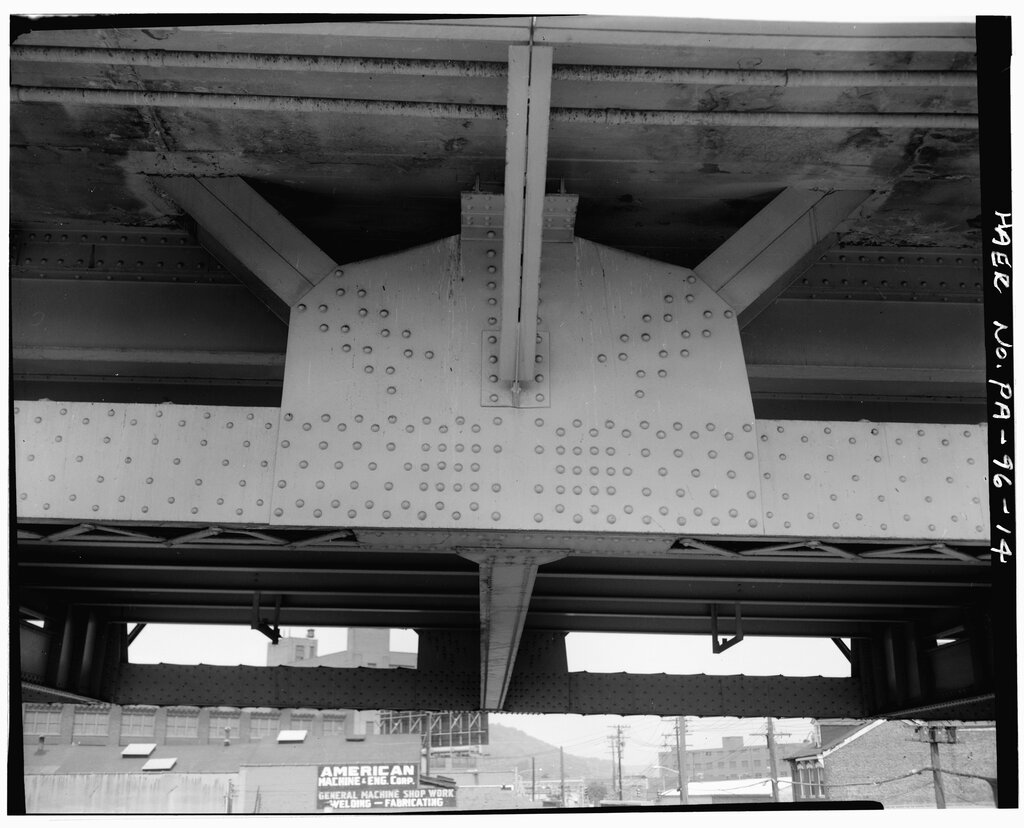
When wind pushes on the side of a building, it creates a lateral load that tries to bend the entire structure. In a building with moment-resisting joints, the beams and columns work together as a rigid frame to resist this bending. The load travels through the floor slabs (acting as diaphragms), into the moment frames or shear walls, and then down to the foundation. Without these rigid connections, a building would be far more susceptible to swaying or even collapsing under strong winds.
Understanding how to trace these vertical and lateral load paths is the core of structural analysis. It allows an engineer to see the building not as a static object, but as a dynamic system of interconnected parts, each playing a role in channeling forces safely to the earth.
What is the primary purpose of a load path in a structure?
The concept of "tributary area" is used to determine: