Intermediate Electrical Systems and Analysis
Advanced Circuit Analysis
Power, Heat, and Resistance
You already know that voltage drives current through a resistance. But what is the consequence of that electron flow? As current navigates the resistive path of a component, electrical energy is converted into another form, usually heat. This rate of energy conversion is called power.
By combining this with Ohm's Law (), we can express power in terms of resistance. These alternative forms are often more direct for circuit analysis.
In circuit design, power isn't just about what you supply; it's about what you dissipate. Every component that resists current flow will generate heat, a factor that is critical to a circuit's reliability and lifespan.
Choosing the Right Resistor
When you select a resistor for a circuit, its resistance value is only half the story. You also need to consider its tolerance and power rating. Tolerance tells you how accurate the resistor's stated value is, while the power rating specifies the maximum amount of heat it can safely dissipate before it fails.
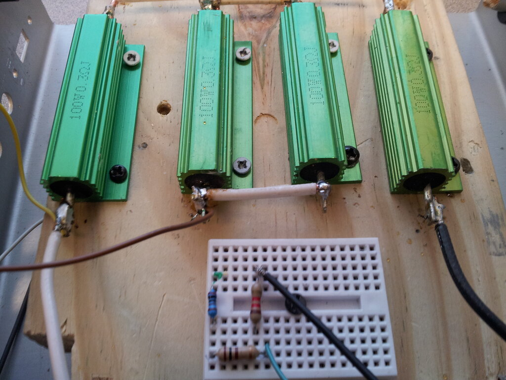
For common axial resistors, these properties are indicated by a series of colored bands. Let's look at a typical four-band resistor.
| Band Color | 1st Digit | 2nd Digit | Multiplier | Tolerance |
|---|---|---|---|---|
| Black | 0 | 0 | 10⁰ (x1) | - |
| Brown | 1 | 1 | 10¹ (x10) | ±1% |
| Red | 2 | 2 | 10² (x100) | ±2% |
| Orange | 3 | 3 | 10³ (x1k) | - |
| Yellow | 4 | 4 | 10⁴ (x10k) | - |
| Green | 5 | 5 | 10⁵ (x100k) | ±0.5% |
| Blue | 6 | 6 | 10⁶ (x1M) | ±0.25% |
| Violet | 7 | 7 | - | ±0.1% |
| Gray | 8 | 8 | - | - |
| White | 9 | 9 | - | - |
| Gold | - | - | 10⁻¹ (x0.1) | ±5% |
| Silver | - | - | 10⁻² (x0.01) | ±10% |
For a 4-band resistor: the first two bands represent the significant digits, the third is the multiplier, and the fourth is the tolerance. For example, a resistor with bands Yellow-Violet-Red-Gold is a 4700 Ω or 4.7 kΩ resistor with a ±5% tolerance. This means its actual resistance could be anywhere from 4465 Ω to 4935 Ω.
Choosing tolerance is a trade-off. A tighter tolerance (like ±1%) gives you more predictable circuit behavior but costs more. For non-critical applications like an LED indicator, a ±10% tolerance is fine. For a precision voltage reference, you'd need a much tighter tolerance.
Real-World Complications
Ideal resistors have a constant resistance value. Real resistors, however, change their resistance with temperature. This property is defined by the (TCR), usually specified in parts per million per degree Celsius (ppm/°C).
A resistor with a TCR of +100 ppm/°C will increase its resistance by 0.01% for every 1°C rise in temperature. In a sensitive measuring device exposed to fluctuating ambient temperatures, this drift can be a significant source of error.
This brings us back to power. The heat generated by a resistor () increases its temperature, which in turn can alter its resistance, affecting the entire circuit. This is why selecting the right power rating is so important.
A standard rule of thumb is to choose a resistor with a power rating at least double the expected maximum power dissipation. If your calculations show a resistor will dissipate 0.2 watts, you should use a 1/2-watt (0.5 W) resistor, not a 1/4-watt (0.25 W) one. This safety margin, known as , ensures the component doesn't overheat, which improves reliability and extends its lifespan. Overlooking this can lead to smoking resistors and failed circuits.
What does electrical power represent in a resistive circuit?
A 4-band resistor has the following color code: Brown, Black, Orange, Silver. What is its nominal resistance and tolerance?