Integrated Electronics and Embedded Systems Engineering
Circuit Analysis Mastery
Mapping Your Circuit's Highways
You already know the basic rules of the road for electrons, like Ohm's Law. Now, it's time to become a traffic engineer for complex circuits. When you're dealing with a printed circuit board (PCB) with multiple power rails and interconnected components, simply looking at resistors in series or parallel isn't enough. We need more powerful tools to understand how voltage and current behave everywhere in the system. The two main methods are Nodal and Mesh analysis.
Nodal analysis is based on Kirchhoff's Current Law (KCL), which states that the total current entering a junction (or node) must equal the total current leaving it. In this method, we identify all the primary nodes in a circuit and assign a voltage variable to each one, relative to a common reference point (usually ground). Then, we write an equation for each node summing the currents flowing in and out. Solving this system of equations gives us the voltage at every key point in the circuit.
Think of it this way: Nodal analysis focuses on the destinations (the voltage at each junction), while Mesh analysis focuses on the journeys (the current in each loop).
Mesh analysis, on the other hand, uses Kirchhoff's Voltage Law (KVL). KVL tells us that the sum of all voltage drops around any closed loop in a circuit must be zero. To use this method, we identify all the independent loops, or "meshes," in a circuit and assign a circulating current to each one. By writing a KVL equation for each mesh, we create a system of equations that can be solved to find the current flowing through every part of the circuit. This technique was pioneered by physicist Gustav Kirchhoff in the 19th century.
Choosing the Right Power Source
In any embedded system, you'll need to convert a source voltage (like from a battery or wall adapter) into the specific, stable voltages your components require. A microcontroller might need 3.3V, while a sensor needs 5V. The components that perform this task are called voltage regulators. The two most common types are Low-Dropout (LDO) regulators and switching regulators.
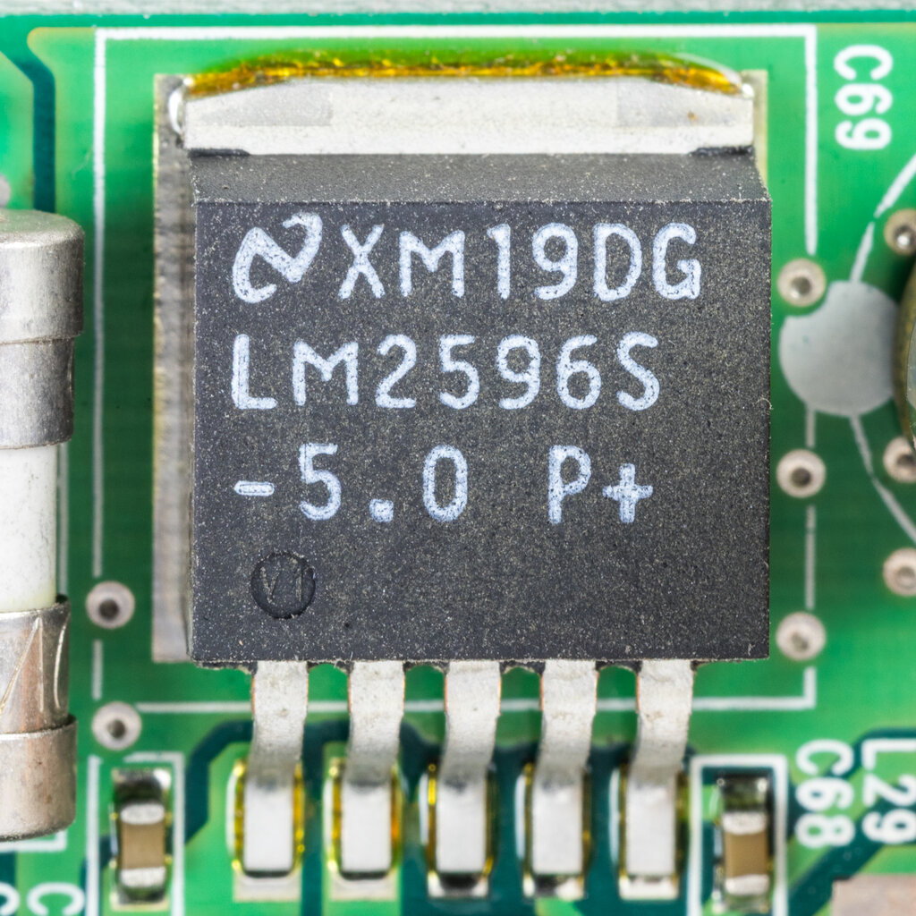
An LDO is a type of linear regulator. It works like a variable resistor, constantly adjusting its resistance to dissipate excess energy as heat, resulting in a stable output voltage. They are simple, inexpensive, and produce very little electrical noise, making them ideal for powering sensitive analogue components. However, their efficiency is poor, especially when there's a large difference between the input and output voltage. All that dissipated energy is wasted power.
Switching regulators are far more efficient. Instead of burning off excess power, they rapidly switch the input voltage on and off, using inductors and capacitors to store and release energy to produce a smooth, stable output. They can step voltage down (a buck converter), step it up (a boost converter), or both. Their high efficiency makes them perfect for battery-powered devices where every milliamp matters. The trade-off is that they are more complex, expensive, and the high-speed switching generates electrical noise that can interfere with other parts of your circuit if not managed properly. The minimum required voltage difference for an LDO to operate is called its dropout voltage
| Feature | LDO Regulator | Switching Regulator |
|---|---|---|
| Efficiency | Low (especially with large V_in/V_out difference) | High (often >90%) |
| Noise/Ripple | Very Low | High (requires filtering) |
| Complexity | Simple (few external components) | Complex (requires inductor, capacitors) |
| Cost | Low | Higher |
| Best For | Powering sensitive analogue parts, low-power logic | Battery-powered devices, high-power applications |
Keeping Signals Clean
Digital circuits might seem like they only care about 1s and 0s, but the analogue reality is messy. High-speed switching in components like microcontrollers and switching regulators creates high-frequency noise that travels along power and signal lines. This noise can cause unpredictable behaviour, making your system unreliable. We use passive filters, most commonly just capacitors, to clean this up.
Every digital signal is fundamentally an analogue signal. Signal integrity is the practice of making sure that analogue reality matches the digital ideal.
This is where decoupling and bypass capacitors come in. Though the terms are often used interchangeably, they have slightly different jobs. A is placed close to a power source to shunt high-frequency noise to ground, preventing it from travelling further into the circuit. A decoupling capacitor is placed as close as possible to the power pin of an integrated circuit (IC). Its job is to act as a tiny, local energy reservoir, supplying the instantaneous current an IC needs when it switches states. This prevents the switching action from causing a momentary voltage dip (or "droop") on the power rail, which could affect other ICs.
Selecting the right capacitor involves more than just picking a capacitance value. You also need to consider its voltage rating and its Equivalent Series Resistance (ESR), which affects how effectively it can filter noise at high frequencies. A typical strategy is to use a larger electrolytic or tantalum capacitor (1-10μF) for bulk bypassing of the main power rail, combined with smaller ceramic capacitors (0.1μF or 100nF) for decoupling at each individual IC.
Bridging Voltage Gaps
It's rare for every component in an embedded system to run on the same voltage. You might have a 3.3V microcontroller trying to communicate with a 5V sensor, or trying to drive a 12V motor. Directly connecting them can damage the lower-voltage component. The solution is logic level shifting, and one of the simplest ways to do this is with a transistor.
A common NPN bipolar junction transistor (BJT) can act as a simple switch. When a small current is applied to its base (from our 3.3V microcontroller's output pin), it allows a much larger current to flow from its collector to its emitter. We can use this to control a higher-voltage device. For example, we can connect a 12V motor to the collector and ground the emitter. When the microcontroller outputs a 3.3V 'high' signal to the transistor's base, the switch 'closes', and the 12V motor turns on.
This setup works well for turning things on and off, but for bidirectional communication (like with an I2C bus), you need a more sophisticated circuit, often involving MOSFETs. Dedicated level-shifter ICs are also available that handle all the complexity for you in a single, convenient package.
Let's check your understanding of these circuit analysis techniques.
Which circuit analysis technique is fundamentally based on Kirchhoff's Current Law (KCL) and involves solving for unknown voltages at various points in a circuit?
You need to power a sensitive analogue audio component that requires a very clean, low-noise power supply. Efficiency is not the primary concern. Which type of voltage regulator would be the most suitable choice?
With these analysis techniques, you're now equipped to move beyond simple circuits and start designing the robust power and signal paths required for professional embedded systems. The next step is to translate these circuits from theory into a physical layout.