Industrial PLC Programming and Automation Systems
Hardware Interfacing Principles
The Physical-to-Digital Bridge
A PLC's real power comes from its ability to interact with the physical world. This connection happens through Input/Output (I/O) modules. Think of them as translators, converting electrical signals from sensors into data the CPU can understand, and turning the CPU's commands back into electrical signals for actuators.
Every wire from a sensor or to an actuator connects to a specific screw on a terminal block. This terminal is the physical entry point to the PLC system. From there, the signal travels to an I/O module, which handles the translation. But getting this connection right is crucial, and it starts with understanding how electricity needs to flow.
Sinking vs. Sourcing
In DC circuits, which are standard for PLC I/O, current flows from a positive potential to a negative potential. The terms 'sinking' and 'sourcing' describe which part of the circuit provides the power source and which part completes the circuit to ground.
- Sourcing: A sourcing device provides the positive (+) voltage. Current flows out of it to the connected device.
- Sinking: A sinking device provides the path to ground or common (-). Current flows into it from the connected device.
A fundamental rule is that you must always connect a sourcing device to a sinking device. You can't connect a source to a source, or a sink to a sink. This is a common mistake in the field.
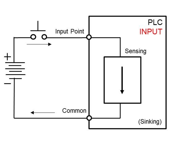
This concept directly applies to sensors and I/O modules. Sensors are often described as PNP or NPN types. A PNP sensor is a sourcing device; it outputs a positive voltage when activated. Therefore, it must be wired to a sinking PLC input module.
Conversely, an NPN sensor is a sinking device; it switches the connection to ground when activated. It must be wired to a sourcing PLC input module. The same logic applies to output modules and the actuators they control. A sourcing output module provides power to an actuator, while a sinking output module completes the actuator's circuit to ground.
From Physical Wires to Digital Bits
Once a device is correctly wired to a terminal, the I/O module assigns its state to a specific bit in the PLC's memory. This process is called or addressing. Each terminal point corresponds to a unique memory address that your ladder logic program can read from (for inputs) or write to (for outputs).
The addressing format varies between PLC manufacturers, but the concept is universal. An address might look something like I:1/0, which could mean:
- I: This is an Input.
- 1: It's in Slot 1 of the PLC chassis.
- 0: It's connected to Terminal 0 on that module.
When the sensor connected to terminal 0 is activated, the memory bit at address I:1/0 changes from a 0 to a 1. Your program can then use this bit to trigger an action, like starting a motor.
| Terminal | Address | Description |
|---|---|---|
| 0 | I:1/0 | Conveyor Start Button |
| 1 | I:1/1 | Part Present Sensor |
| 2 | I:1/2 | Emergency Stop |
| 3 | I:1/3 | Motor Overload Fault |
| ... | ... | ... |
Handling Analog Signals
Not all signals are simple on/off states. Many sensors measure continuous values like temperature, pressure, or flow. These produce analog signals, which are typically represented by a variable voltage or current. The two most common standards in industry are 0-10V (volts) and 4-20mA (milliamps).
The PLC's CPU can't work directly with volts or milliamps. It needs digital numbers. An analog input module performs this conversion using an (ADC). The ADC reads the incoming signal and converts it into an integer value within a specific range.
This process is called scaling. For example, a 12-bit ADC might convert a 4-20mA signal into a range of integer values from 0 to 4095. In this case:
- A 4mA signal (minimum pressure) becomes the integer 0.
- A 20mA signal (maximum pressure) becomes the integer 4095.
- A 12mA signal (50% of the range) becomes the integer 2047.
Your PLC program must then scale this raw integer value back into a meaningful engineering unit, like PSI or °C, using a simple math instruction. This scaling calculation is a fundamental task in any application involving analog sensors.
Properly interfacing hardware is the foundation of a reliable automation system. By understanding how to correctly wire sinking and sourcing devices, map physical terminals to memory, and scale analog signals, you ensure the data your program uses is an accurate reflection of the real world.