High Voltage Power Line Design
High-Voltage Power Line Design Fundamentals
The Grid’s Superhighways
Power plants are often located far from the cities and towns that need electricity. Getting that power from point A to point B efficiently is a huge challenge. Think of it like water in a hose. If you use a very thin hose (low voltage), you lose a lot of pressure (energy) to friction, especially over long distances. But if you use a wide, high-pressure pipe (high voltage), the water flows much more easily.
Electricity works similarly. When we transmit power, some of it is lost as heat due to the resistance of the wires. The amount of power lost is proportional to the square of the current (). To minimize this loss, we need to make the current () as low as possible. Since power is the product of voltage and current (), we can decrease the current by dramatically increasing the voltage.
Higher voltage means lower current, and lower current means less energy wasted as heat. This is the fundamental reason we use high-voltage lines for long-distance transmission.
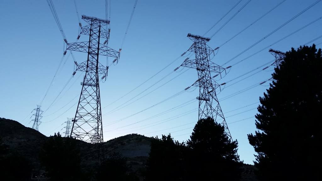
These high-voltage lines act as the superhighways of the electrical grid, moving massive amounts of power across hundreds of miles with minimal loss.
Anatomy of a Power Line
At first glance, a transmission line might just look like wires on a tall tower. But each part is carefully engineered to handle immense electrical and physical stress.
- Conductors: These are the actual wires that carry the electric current. They're typically made of aluminum alloys, which offer a good balance of conductivity and light weight.
- Insulators: Electricity at high voltages can jump across the air to find a path to the ground. Insulators, often made of glass or porcelain, prevent the electricity from flowing through the tower itself. The higher the voltage, the longer the string of insulators needs to be.
- Towers: Also called pylons, these structures support the weight of the conductors and keep them safely suspended high above the ground. Their design depends on the voltage, terrain, and number of circuits they need to carry.
- Shield Wires: These are thinner wires running along the very top of the towers. They aren't energized; their job is to intercept lightning strikes and safely conduct the massive surge of electricity to the ground, protecting the current-carrying conductors below.
Key Design Decisions
Designing a high-voltage line involves a series of critical trade-offs. Engineers must balance performance, cost, and safety.
Voltage Level: Choosing the voltage is the first big decision. Voltages like 230,000 volts (230 kV) or 500,000 volts (500 kV) are common. Higher voltages are more efficient for very long distances but require taller towers, more insulation, and a wider cleared path, known as a right-of-way. This all adds to the cost.
Line Capacity: How much power does the line need to carry? This determines the size and number of conductors. A line designed to power a large city needs much thicker conductors than one serving a smaller town. This capacity is known as ampacity, the maximum current a conductor can handle before overheating.
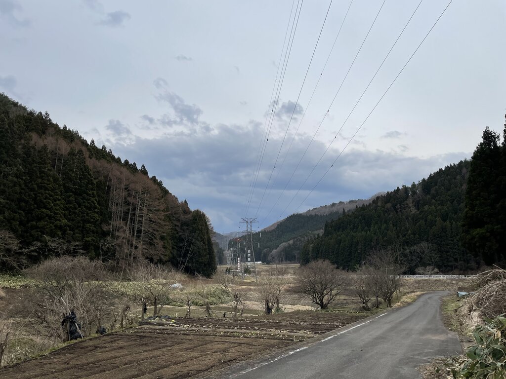
Environmental Factors: The path of the line is rarely a straight shot. Designers must account for mountains, valleys, rivers, and existing infrastructure. Weather is also a huge factor. Lines in northern climates must be strong enough to withstand heavy ice and snow, while lines in coastal areas need to resist corrosion from salt spray.
A Mechanical and Electrical Balancing Act
Ultimately, power line design is a two-sided problem. On one hand, it's a mechanical challenge. The towers and conductors must be physically strong enough to support their own weight and endure decades of stress from wind, ice, and temperature changes. A line that sags too much on a hot day could be a safety hazard, while a tower that can't handle a winter storm could cause a major outage.
On the other hand, it's an electrical challenge. Beyond simply moving power, designers have to manage complex electrical phenomena.
One such phenomenon is corona discharge, a loss of energy that occurs when the voltage on a conductor is high enough to ionize the air around it. This can create a faint violet glow and a distinct buzzing or hissing sound.
Engineers work to minimize these effects, ensuring the line is not just strong, but also electrically stable and efficient. This involves carefully selecting conductor types, spacing, and configurations to deliver power reliably.
Now, let's test your understanding of these core concepts.
Why is electricity transmitted at very high voltages over long distances?
What is the primary function of the glass or porcelain discs found on transmission towers?
With these fundamentals in mind, we can start to explore the more specific details of how these incredible structures are engineered.