Engineering Graphics and Solid Drawing Essentials
Introduction to Engineering Graphics
A Language for Builders
Long before engineers wrote code or ran complex simulations, they drew. Engineering graphics are a universal language, allowing a designer in one country to communicate precise instructions to a builder in another without a single spoken word. This visual language has been essential for centuries.
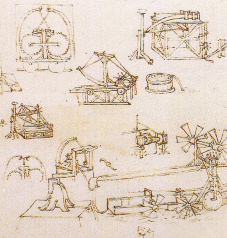
Early innovators like Leonardo da Vinci filled notebooks with incredible designs for flying machines and weapons. His drawings were revolutionary, but they were personal. They were sketches of ideas, not formal instructions that someone else could easily follow to build the object exactly as intended.
The Industrial Revolution changed everything. As factories began mass-producing goods, the need for consistency became critical. Eli Whitney's concept of interchangeable parts for firearms was a turning point. For parts to be interchangeable, they had to be manufactured to the same exact specifications. This required a new level of precision in communication, something words alone couldn't provide. Drawings had to become standardized and unambiguous.
Around the same time, French mathematician Gaspard Monge developed descriptive geometry. This provided the mathematical foundation for representing three-dimensional objects on a two-dimensional surface, a core principle of modern technical drawing. Engineering graphics evolved from artistic sketches into a rigorous, rule-based system.
Why a Picture Is Worth a Thousand Parts
An engineering drawing is far more than just a picture; it's a complete set of instructions. It communicates all the necessary information to transform an idea into a physical object. This includes:
- Geometry: The shape and features of the object.
- Dimensions: The exact size and location of all features.
- Tolerances: The acceptable variation for each dimension.
- Material: What the object is made of.
- Finish: The desired surface quality.
Think of it like a musical score. A composer doesn't just write a melody; they specify the key, tempo, dynamics, and which instruments play which notes. The score is a complete guide for the orchestra. An engineering drawing does the same thing for a manufacturing team. It ensures that the final product, whether it's a simple bolt or a complex jet engine, matches the designer's intent perfectly.
Use 2D CAD to produce detailed technical drawings to communicate design intent to manufacturing teams.
The Rules of the Road
To be a universal language, engineering graphics needs a shared grammar and vocabulary. This is where standards come in. Standards are sets of rules that govern how technical drawings are created, ensuring they are clear, consistent, and interpreted the same way by everyone.
| Standard | Full Name | Primary Region of Use |
|---|---|---|
| ANSI | American National Standards Institute | United States |
| ISO | International Organization for Standardization | Worldwide, especially Europe |
| ASME | American Society of Mechanical Engineers | United States (often used for mechanical engineering) |
These organizations define everything from the types of lines to use, how to format dimensions, and what symbols mean. For example, a thick, solid line represents a visible edge of an object, while a dashed line represents a hidden edge. Without these standards, a drawing would be open to interpretation, leading to confusion, costly errors, and parts that don't fit together.
Adhering to standards ensures that a design can be shared globally across different companies and teams, with everyone working from the same set of clear instructions.
From T-Squares to Pixels
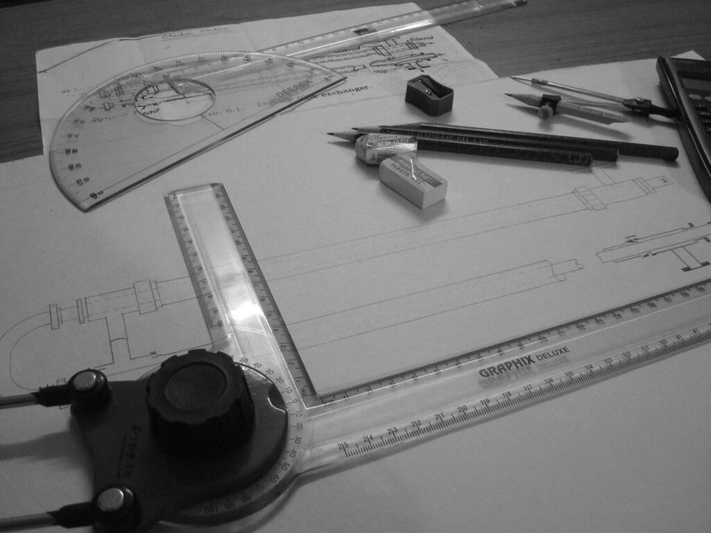
The tools used to create engineering drawings have evolved dramatically. For decades, drafting was a manual process done on a drawing board. Engineers used tools like T-squares, triangles, compasses, and specialized pencils to create precise drawings by hand. It was a meticulous skill that required a steady hand and a deep understanding of geometric principles.
Today, most engineering graphics are created using Computer-Aided Design (CAD) software. CAD software allows engineers to create highly accurate 2D drawings and 3D models digitally. This transformation from board to screen has revolutionized the field.
With CAD, designers can work faster, make changes easily, and explore complex designs that would be nearly impossible to draw by hand. The software automates many of the tedious tasks of manual drafting, like drawing standard symbols or calculating dimensions. It also allows for the creation of 3D models that can be rotated, analyzed for stress, and even used to 3D print a prototype before manufacturing begins.
While the tools have changed, the fundamental principles of clear visual communication remain the same. The goal is still to create an unambiguous guide for turning an idea into reality.
Ready to check your understanding? This quiz will test you on the core ideas we've covered.
What was the primary reason for the shift from personal sketches, like those of Leonardo da Vinci, to standardized engineering drawings during the Industrial Revolution?
The work of French mathematician Gaspard Monge was crucial to the development of modern technical drawing because it provided:
Understanding these foundations is the first step in learning to read and create the blueprints that build our world.