Engineering Drawing Line Projections
Introduction to Engineering Drawing
The Language of Engineering
An engineering drawing is a detailed, precise plan that communicates how to make something. Think of it as a universal language. An engineer in one country can create a drawing for a new phone, and a manufacturer on the other side of the world can use that drawing to build it exactly as intended. It’s the bridge between an idea and a physical object.
The core purpose of these drawings is to capture a three-dimensional object on a two-dimensional surface, like a piece of paper or a computer screen. This isn’t just a simple sketch. It’s a technical document packed with information, specifying the object's exact size, shape, materials, and finish.
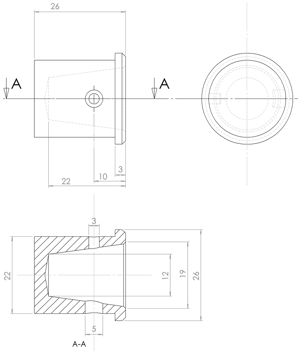
Every line and symbol on an engineering drawing has a specific meaning. There’s no room for artistic interpretation; clarity and precision are the goals.
Tools of the Trade
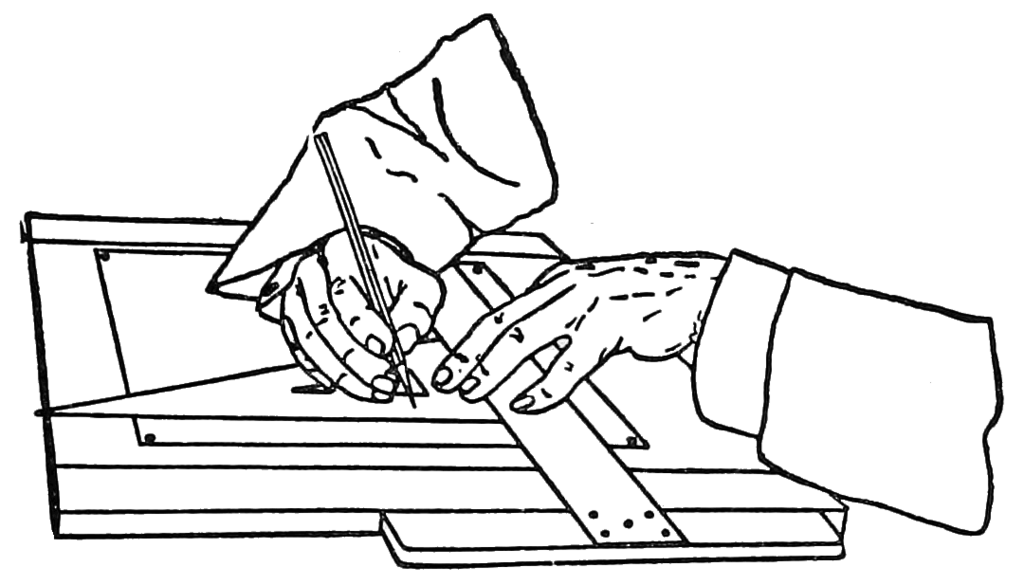
Historically, technical drawings were created by hand using specialized tools. Draftspeople used T-squares to draw horizontal lines, triangles for vertical and angled lines, and compasses for circles and arcs. Pencils of varying hardness created lines of different weights and thicknesses. This manual process required immense skill and patience.
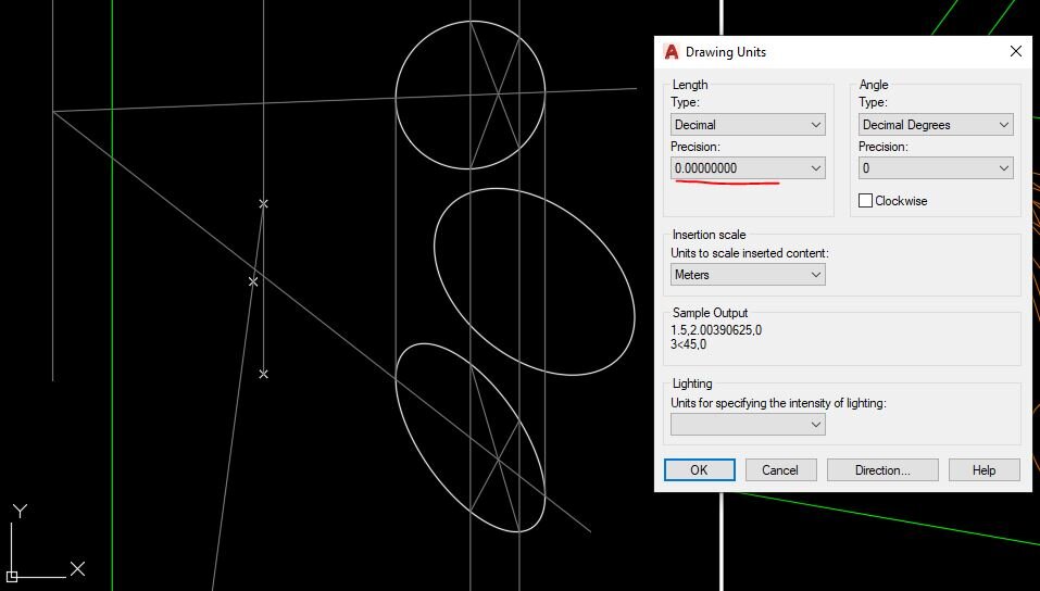
Today, most engineering drawings are created using Computer-Aided Design (CAD) software. Programs like AutoCAD, SolidWorks, and Fusion 360 allow designers to create 2D drawings and 3D models with incredible speed and accuracy. While the tools have changed, the fundamental principles of clear communication remain exactly the same. CAD simply makes it easier to create, edit, and share these precise plans.
Rules of the Road
To ensure anyone can read a drawing correctly, engineers follow a set of established rules and conventions. One of the most basic is the use of different line types. Each style of line has a distinct purpose and communicates a different piece of information about the object.
These conventions are part of larger standards, such as those from the American National Standards Institute (ANSI) or the International Organization for Standardization (ISO). These organizations ensure that the symbols and rules used in engineering drawings are consistent worldwide, preventing costly misunderstandings.
Scale and Dimensions
It’s rarely practical to draw an object at its actual size. You can't fit a drawing of a bridge on a piece of paper, and a drawing of a tiny computer chip would be too small to read. This is where scale comes in.
Scale
noun
The ratio between the size of an object on a drawing and its actual size in real life.
The scale is always noted on the drawing. A scale of 1:2 means the drawing is half the size of the actual object. A scale of 2:1 means the drawing is twice the size of the object. This allows massive or minuscule objects to be represented clearly on a standard-sized sheet.
While scale gives the drawing its proportions, dimensions provide the exact sizes needed for manufacturing. Dimensions are numerical values that specify the length, width, height, and diameter of each feature of the object. They are shown using dimension lines with arrows, clearly indicating what part of the object is being measured.
Even if a drawing is not to scale, the written dimensions are always the true measurements that must be followed.
Mastering these basics—understanding the purpose, tools, conventions, and notation—is the first step in learning to read and create the blueprints that build our world.
What is the primary purpose of an engineering drawing?
Which of the following is an example of modern software used to create engineering drawings?