Digital Logic Design and Analysis
Logic Optimization
From Algebra to Efficiency
You already know how to use Boolean algebra to describe and manipulate logic. Now, we move from correctness to efficiency. In digital design, simpler is better. A minimized logical expression uses fewer gates, which means a smaller, faster, and more power-efficient circuit. While algebraic manipulation works, it can be tedious and it's easy to miss the most optimal solution. For that, we need a more systematic approach.
Enter the Karnaugh Map, or K-map. It’s a visual tool that arranges a function's truth table into a grid. The magic of the K-map is in its layout. Adjacent cells in the grid differ by only a single input variable. This special arrangement, based on Gray code, makes it easy to spot opportunities for simplification that are hard to see with algebra alone.
Mapping the Logic
Let's start with a 3-variable function. A 3-variable K-map is an 8-cell grid. We'll map the variables A, B, and C to the grid's axes. Notice how the numbering for BC (00, 01, 11, 10) doesn't follow a standard binary count. This is intentional and ensures that any two adjacent cells only differ by one bit.
To simplify, we look for groups of adjacent 1s. The groups must be rectangular and contain a number of cells that is a power of two (1, 2, 4, 8...). Your goal is to cover all the 1s using the largest possible groups. The map wraps around, so the leftmost and rightmost columns are considered adjacent, as are the top and bottom rows in larger maps.
For each group, we find the variables that remain constant. In a group of two, one variable will change and be eliminated. In a group of four, two variables are eliminated, and so on. The final simplified expression is the sum of the terms representing each group.
Bigger groups mean more eliminated variables, which leads to a simpler final expression.
The same logic extends to 4 and 5-variable maps. A 4-variable map is a 4x4 grid. A 5-variable map can be visualized as two 4-variable maps stacked on top of each other, where one map is for the 5th variable being '0' and the other for it being '1'. Adjacency exists not only within each map but also between corresponding cells in the two separate maps.
Prime Implicants and Don't Cares
Each group of 1s on a K-map corresponds to a product term called an implicant. A is a group of 1s that isn't fully contained within any other, larger group. The simplified expression is formed by a selection of these prime implicants.
An essential prime implicant is a prime implicant that covers at least one '1' that no other prime implicant can cover. You must always include all essential prime implicants in your final solution.
Sometimes, certain input combinations will never occur in a circuit. For example, in a system using Binary Coded Decimal (BCD), the binary codes for 10 through 15 (1010 to 1111) are invalid. We can use these as on the K-map, marked with an 'X'.
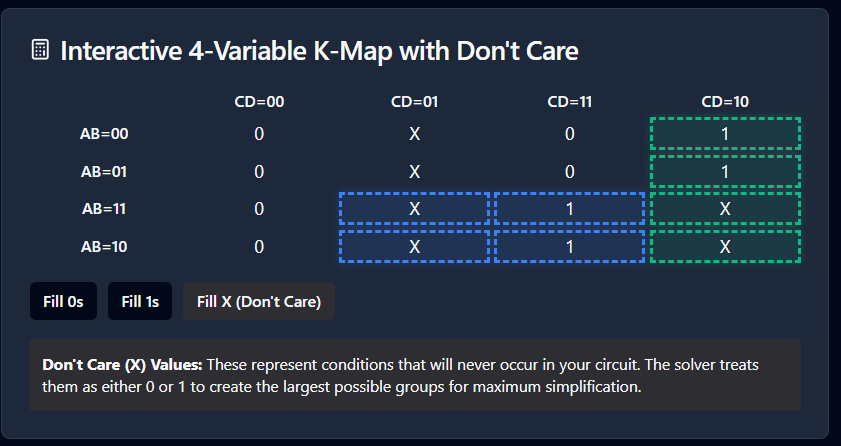
The beauty of a 'don't care' is that you can choose to include it in a group of 1s to make the group larger, or you can ignore it. You use them to your advantage to create the biggest possible groups, leading to maximum simplification.
SOP, POS, and Universal Gates
So far, we've grouped the 1s to create a minimal Sum of Products (SOP) expression. We can also group the 0s. Grouping the 0s gives you the minimal SOP expression for the inverse of the function, . By applying De Morgan's Laws to this inverse expression, you can find the minimal Product of Sums (POS) form for the original function, .
While designs are easiest to think about in terms of AND, OR, and NOT gates, it is often cheaper and simpler to manufacture circuits using only one type of gate. NAND and NOR gates are known as universal gates because any logical function can be constructed using only NAND gates or only NOR gates.
A key trick is that a two-level AND-OR circuit (typical for SOP forms) can be directly converted to a two-level NAND-NAND circuit. Similarly, a two-level OR-AND circuit (for POS forms) converts to a NOR-NOR circuit. This means after you find your minimal SOP expression, you can implement it directly with NAND gates without any further algebraic changes.
Now that you know how to turn complex Boolean expressions into efficient circuits, let's test your understanding.
What is the primary advantage of using a Karnaugh map for Boolean simplification compared to algebraic manipulation?
The cell numbering along the axes of a K-map (e.g., 00, 01, 11, 10) follows a specific sequence. What is the purpose of this arrangement?