Deriving Half Wave Rectifier Output
Input Signal Characteristics
The Input Signal
The input to a half-wave rectifier is typically a sinusoidal alternating current (AC) voltage. This is the same type of voltage that comes from a wall outlet, though often stepped down to a lower level by a transformer. We can describe this voltage mathematically at any given moment in time.
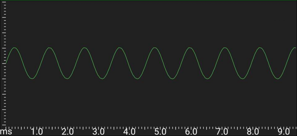
The instantaneous voltage, , changes continuously. Its behavior follows the sine function, oscillating smoothly between a positive maximum and a negative minimum. The equation that models this is fundamental to our analysis.
Analyzing a Full Cycle
To understand how a rectifier interacts with this signal, we need to examine its behavior over one complete cycle. A full cycle of a sine wave corresponds to an angular rotation of radians, or 360 degrees. After this point, the pattern simply repeats.
We are most interested in when the voltage is positive and when it is negative. This is what determines whether the diode in the rectifier circuit will conduct electricity or block it. The key is to partition the waveform into intervals based on its polarity.
The cycle is perfectly symmetrical. It consists of two distinct halves.
Partitioning the Waveform
The first interval, from to , is the positive half-cycle. Throughout this period, the voltage is positive, starting at zero, rising to its peak at , and falling back to zero at . This is the interval where a forward-biased diode will conduct.
The second interval, from to , is the negative half-cycle. Here, the voltage is negative. It decreases to its minimum value, , at , and returns to zero at . During this phase, the diode will be reverse-biased and will block the flow of current.
By defining these boundary conditions, we have set the stage for analyzing the rectifier's output. The behavior of the input signal within these two intervals is all we need to derive the average voltage, current, and overall efficiency of the circuit.