Data Center Infrastructure and Interconnects
High Speed Interconnect Hardware
The Engines of Hyperspeed
As data centers push towards 400G, 800G, and even 1.6T (terabits per second) speeds, the physical limits of copper wires and optical fibers become major hurdles. Simply pushing more bits faster isn't enough. The signals degrade, becoming noisy and unrecognizable over even short distances. To solve this, network hardware had to get smarter, not just faster.
The first step was to change how we encode data. For years, networks used a simple method called Non-Return-to-Zero (NRZ). It used two voltage levels, one for a '0' and another for a '1'. It was reliable and straightforward, but it hit a wall. Doubling the data rate meant doubling the frequency, which drastically increased signal loss and noise.
The solution is PAM4 modulation. Instead of two voltage levels, PAM4 uses four, allowing it to pack two bits of information into a single symbol. This masterstroke doubles the data rate without doubling the signal's fundamental frequency, known as the baud rate. It's the key technology that makes 800G and 1.6T possible, but it comes with a trade-off: the four voltage levels are much closer together, making the signal far more susceptible to noise. Distinguishing between a '01' and a '10' becomes incredibly difficult without advanced processing.
The DSP and the Art of Signal Recovery
This is where the Digital Signal Processor (DSP) becomes the hero. A DSP is a specialized microchip inside a high-speed transceiver that reconstructs the fragile PAM4 signal. Think of it as a powerful audio engineer cleaning up a noisy recording. It performs several critical functions.
First, it performs Clock and Data Recovery (CDR). It analyzes the incoming, messy waveform and locks onto the underlying timing of the signal, essentially finding the 'beat'. Then, it samples the signal at the perfect moment in each cycle to decide which of the four voltage levels it represents.
Second, the DSP applies Electronic Dispersion Compensation (EDC). As a signal travels down a fiber or copper cable, different frequency components travel at slightly different speeds, causing the signal to spread out and blur—a phenomenon called dispersion This can make it impossible to tell one symbol from the next. The DSP runs complex algorithms that act like a digital lens, computationally reversing the dispersion and refocusing the signal back to its original sharp form.
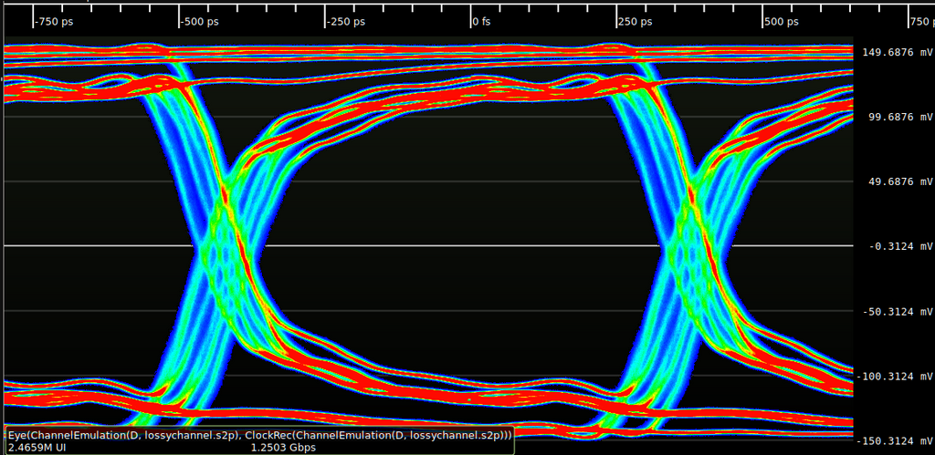
Finally, the DSP manages Forward Error Correction (FEC). Even with advanced recovery, some bits will be misread. FEC adds extra data to the signal that allows the receiver to detect and correct a certain number of errors on the fly, without needing to ask for a retransmission. This is essential for maintaining a stable, low-error link at 400G and beyond. The type of FEC used depends on the link's needs, offering a trade-off between error-correcting power and latency.
| FEC Type | Description | Use Case |
|---|---|---|
| Bypass FEC (No FEC) | The FEC function is turned off. | Lowest latency, for very short, high-quality links where errors are not expected. |
| RS-FEC (KP4) | Reed-Solomon FEC. A standard, strong error correction algorithm. | The workhorse for most long-reach optical links (e.g., 10km). Balances correction and latency. |
| Segmented/Concatenated FEC | Combines multiple FEC codes for even stronger error correction. | Ultra-long-haul or very noisy links where maximum error resilience is required, at the cost of higher latency. |
Pluggable Optics and the Power Dilemma
All this processing is housed inside a transceiver, a small, pluggable module that converts electrical signals from a switch into optical signals for fiber, and vice versa. For today's highest speeds, two form factors dominate: the QSFP-DD (Quad Small Form-factor Pluggable Double Density) and the OSFP (Octal Small Form-factor Pluggable). Both are designed to handle the 8 electrical lanes needed for 800G, but the slightly larger OSFP can dissipate more heat, making it suitable for optics with higher power consumption, like those used for long-distance coherent communication.
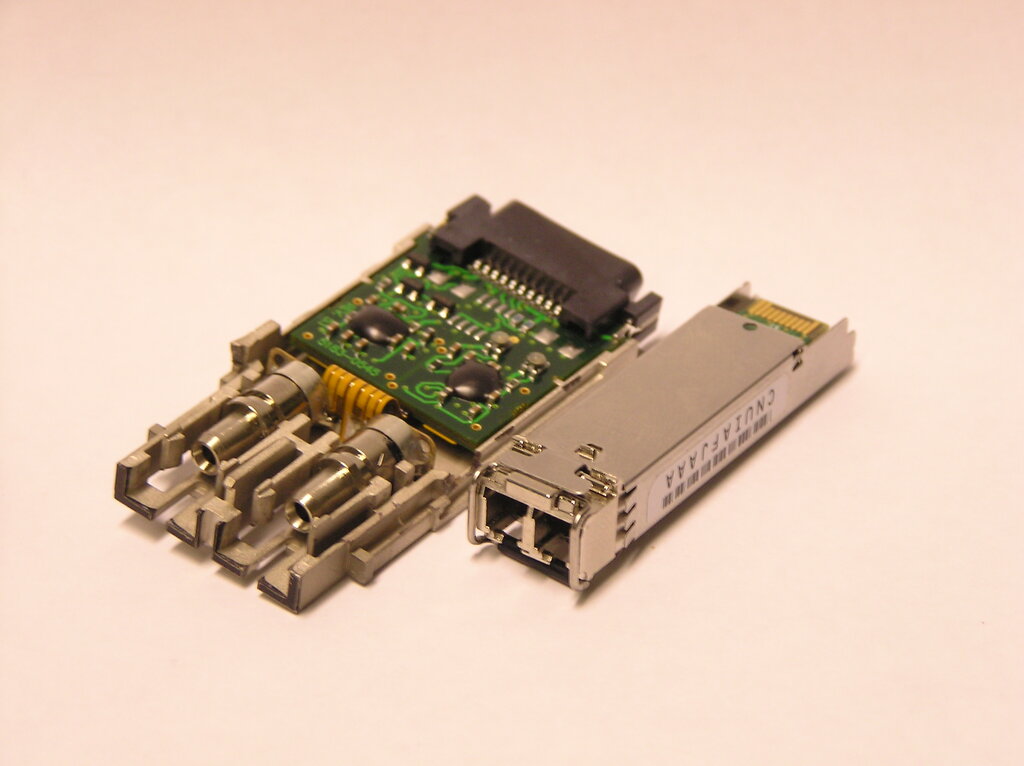
The powerful DSP inside these modules is a major source of heat and power consumption. A single 800G transceiver can consume over 15 watts. In a data center with tens of thousands of ports, this adds up to a massive power and cooling challenge. This has led to an innovative alternative: Linear Drive Pluggable Optics (LPO).
LPO modules remove the DSP from the transceiver entirely. Instead, they use a simple, low-power linear amplifier. The heavy lifting of signal recovery and error correction is offloaded to the main ASIC (the central chip) of the network switch itself. This approach dramatically reduces the power consumption of the pluggable optic, often by more than 50%.
However, it's not a free lunch. This architecture only works for very short distances, typically under 3 meters over copper cables or very short fiber runs. The switch's ASIC must have an extremely powerful, built-in DSP capable of handling the raw, unconditioned signal from the port. It creates a tight coupling between the switch and the optic, as performance depends entirely on the host system's capabilities.
As communication rates surge from 100G to 400G and even higher to 1.6T,the performance of Serdes/DSP/Retimer chips directly determines the efficiency and reliability of communication systems.
The choice between a traditional, fully-retimed DSP-based optic and an LPO module is a critical design decision in modern data centers. For long connections between racks or buildings, the powerful DSP-based optic is the only option. But for the dense, short-reach connections inside a single rack, LPO offers a compelling path to reduce power consumption and cooling costs, a crucial factor in building sustainable, hyperscale infrastructure.
What is the primary advantage of using PAM4 modulation over traditional NRZ for high-speed data transmission?
In a high-speed transceiver, what is the main function of the Digital Signal Processor (DSP)?