CSLB C10 Exam Audio Masterclass
Grounding and Bonding
The Grounding Conductor Hierarchy
NEC Article 250 establishes a precise hierarchy of conductors to ensure safety and system stability. Confusing their roles is a common point of failure on the C-10 exam. Let's differentiate them clearly.
The grounded conductor, typically the neutral, is a current-carrying conductor that is intentionally grounded at the service. Its primary purpose is to complete the normal circuit path for line-to-neutral loads. It is sized according to Article 220 load calculations and subject to adjustments in 220.61.
The Grounding Electrode Conductor (GEC) connects the system grounded conductor (or the equipment) to the grounding electrode or grounding electrode system. It is not intended to carry current except during fault conditions or lightning events. Its sole job is to connect the electrical system to the earth.
Finally, the Equipment Grounding Conductor (EGC) connects the non-current-carrying metal parts of equipment, raceways, and other enclosures to the system grounded conductor and the GEC. The EGC provides the low-impedance path necessary to facilitate the operation of the overcurrent protective device during a ground fault. This is the that Article 250 is built around.
Sizing Critical Conductors
Sizing the GEC and EGC is not based on load, but on the size of the service conductors or the rating of the overcurrent device. This is because their function relates to fault conditions, not normal operation.
GEC Sizing
The GEC is sized based on the size of the largest ungrounded service-entrance conductor, according to NEC Table 250.66. Remember that if the GEC is connected to a concrete-encased electrode, it is not required to be larger than 4 AWG copper.
| Size of Largest Ungrounded Service Conductor (Copper) | Size of GEC (Copper) |
|---|---|
| 2 AWG or smaller | 8 AWG |
| 1 or 1/0 AWG | 6 AWG |
| 2/0 or 3/0 AWG | 4 AWG |
| Over 3/0 AWG through 350 kcmil | 2 AWG |
| Over 350 kcmil through 600 kcmil | 1/0 AWG |
| Over 600 kcmil through 1100 kcmil | 2/0 AWG |
| Over 1100 kcmil | 3/0 AWG |
EGC Sizing
The EGC is sized based on the rating or setting of the overcurrent device ahead of the circuit, as detailed in NEC Table 250.122. This is because the EGC must be able to carry enough fault current to trip that specific device without being destroyed.
For parallel conductor installations, a full-sized EGC must be run in each raceway, sized from Table 250.122 based on the feeder's overcurrent protection.
| Rating of Overcurrent Device (Amps) | Size of EGC (Copper) |
|---|---|
| 15 | 14 AWG |
| 20 | 12 AWG |
| 60 | 10 AWG |
| 100 | 8 AWG |
| 200 | 6 AWG |
| 400 | 3 AWG |
| 600 | 1 AWG |
| 1000 | 2/0 AWG |
| 2000 | 250 kcmil |
Bonding Jumpers and System Integrity
Bonding ensures electrical continuity between all metallic parts in a system that are likely to become energized. The Main Bonding Jumper (MBJ) is the critical connection at the service between the grounded conductor and the equipment grounding conductor. It is sized according to 250.28(D) based on the size of the service-entrance conductors. At a separately derived system, a similar connection called a System Bonding Jumper is required and sized per 250.30(A) and Table 250.102(C)(1).
Bonding also extends to other metallic systems. Metal water piping systems must be bonded, with the jumper sized from Table 250.102(C)(1). If the GEC connects to a grounding electrode downstream of the water meter, a bonding jumper must also be installed around the meter. Structural steel that is part of the building frame must also be bonded to the service equipment.
California Specifics: Ufer and Beyond
California has specific, stringent requirements that go beyond the base NEC. Chief among these is the mandatory use of a concrete-encased electrode, commonly known as a , for all new buildings with a concrete foundation (per CEC 250.52(A)(3)). This electrode must consist of at least 20 feet of 1/2-inch rebar or 4 AWG bare copper wire, encased in at least 2 inches of concrete that is in direct contact with the earth.
This requirement stems from the superior performance of Ufer grounds, which provide a large, stable surface area in contact with the earth, resulting in a consistently low-impedance connection.
Additionally, all services must have an (IBT) accessible on the outside of the building for other low-voltage systems like telephone and CATV to connect their grounding conductors. This ensures all grounded systems are bonded to a common point, minimizing potential differences between them during transient events.
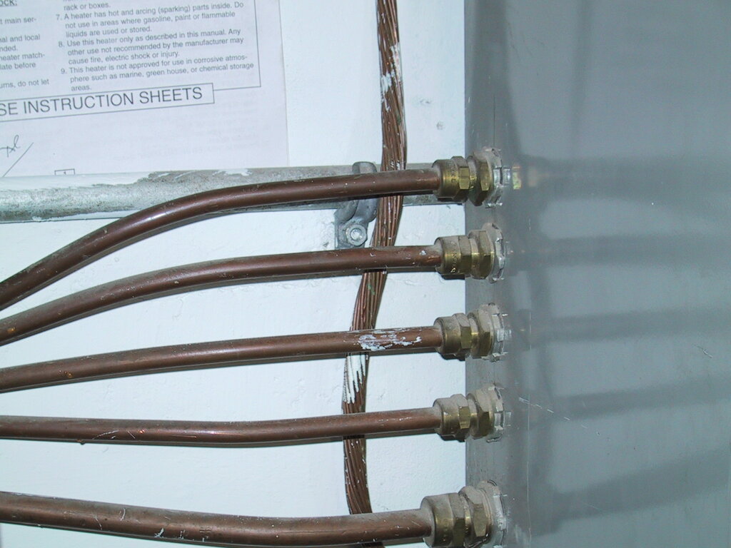
Understanding these specific rules for GECs, EGCs, bonding jumpers, and California-mandated electrodes is crucial. The exam will present complex scenarios, such as sizing conductors for parallel runs or bonding jumpers for multiple interconnected metallic systems, and you must be able to apply the correct NEC table and rules without hesitation.
Which conductor is intentionally grounded and serves as the normal current-carrying path for line-to-neutral loads?
The size of an Equipment Grounding Conductor (EGC) is determined based on what?
Mastering Article 250 is less about memorization and more about understanding the distinct purpose of each component in the ground-fault current path.