Civil 3D Advanced Infrastructure Engineering
Complex Corridor Modeling
Beyond the Single Baseline
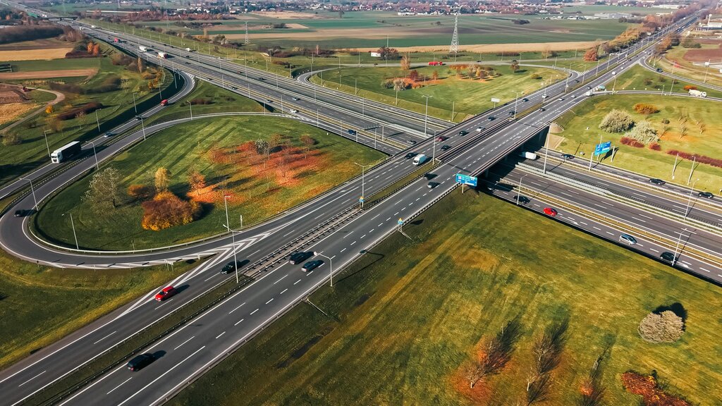
Simple corridors follow a single path, or baseline. But real-world projects are rarely so simple. Intersections, highway interchanges, and even cul-de-sacs require a model that can follow multiple paths at once. This is where multi-baseline corridors come in.
A multi-baseline corridor is a single, unified object built from several different alignments and profiles. Instead of creating separate models for the main road, the intersecting street, and the turning lanes, you can combine them. This creates a cohesive, dynamic model where changes to one alignment automatically update the entire intersection.
Think of it like a skeleton. A single-baseline corridor has one spine. A multi-baseline corridor has a spine, arms, and legs, all connected and moving together.
The key is to add new baselines to your existing corridor object. Each baseline consists of an alignment (the horizontal path) and a profile (the vertical path). By defining different regions along these baselines, you can assign specific assemblies to build out complex shapes like curb returns and splitter islands.
Advanced Targeting
Corridor assemblies are built from subassemblies, and many of these subassemblies need a target to define their width, elevation, or slope. While alignments and profiles are common targets, you can gain much more precision by targeting other objects like or even simple 2D polylines.
Imagine you're designing a road adjacent to a parking lot. The edge of the parking lot isn't a straight line; it's a complex shape defined by parking stalls and islands. You can use a feature line that represents the exact edge of the pavement. By telling your sidewalk or curb subassembly to target this feature line for its width, the corridor will extend precisely to the parking lot edge, no matter how complex its shape.
This method is incredibly powerful. You can target polylines to define the extent of a topsoil stripping area or target feature lines to control the bottom elevation of a retaining wall foundation. It moves your model from being purely theoretical to being directly tied to other design elements in your project.
Gaining Vertical Control
Sometimes, the vertical design of one element depends on another, more complex element. For example, a drainage ditch running alongside a road might need its bottom elevation to be exactly two feet below the road's shoulder, even as the shoulder's elevation changes along a vertical curve. Creating a static profile for this is tedious and error-prone.
A more elegant solution is to use Auxiliary Corridors for vertical control. The process involves creating a temporary, simplified corridor for the element you want to reference, like the road shoulder. From this simple corridor, you can generate a surface. This new surface now represents the exact elevation of the road shoulder at every point.
With this auxiliary surface created, you can now design the profile for your drainage ditch. Instead of manually calculating elevations, you can create a profile that samples its elevations directly from the shoulder surface, with a constant offset of negative two feet. Your ditch profile is now dynamically linked to the road. If the road profile changes, the ditch profile updates automatically.
Managing Model Performance
As corridors become more complex, with multiple baselines and intricate targeting, model performance can suffer. Two key strategies help manage this: controlling corridor frequency and adopting strict naming conventions.
determines how often the assembly is inserted along the baseline. On long, straight sections (tangents), you might only need an assembly every 25 or 50 feet. But on tight curves, you need a much higher frequency, perhaps every 5 feet, to model the curve smoothly. Applying different frequencies to different regions of the corridor ensures accuracy where it's needed without bogging down your model with unnecessary calculations on simple sections.
The 'Power of Names' is about clarity. When your intersection model has ten different baselines and dozens of regions, names like 'Baseline-1' and 'Region-4' become meaningless. Clear naming conventions are essential for managing this complexity.
Adopt a system. For example, name your curb return baselines something like 'INT-MainSt-MapleAve-NEReturn'. Name a region for a bus bay 'Region-BusBay-Sta10+00-12+50'. This practice makes the model understandable to you and your colleagues. It allows you to quickly find and edit a specific part of a massive corridor without having to click through dozens of unnamed elements.
Now, let's test your understanding of these advanced corridor concepts.
What is the primary advantage of using a multi-baseline corridor to model a complex intersection?
You are designing a road that runs alongside an existing, irregularly shaped parking lot. What is the most precise method to make your new curb and sidewalk subassemblies extend perfectly to the edge of the parking lot pavement?