Cisco Network Essentials
Networking Fundamentals
Models for Networking
To understand how computers talk to each other, it helps to use a model. Think of it like building a house. You don't just start nailing boards together; you follow a blueprint that separates the job into logical steps: foundation, framing, plumbing, electrical, and so on. In networking, we use conceptual models to break down the complex process of sending data into smaller, manageable layers.
The two most important models are the Open Systems Interconnection (OSI) model and the TCP/IP model. The OSI model is a seven-layer framework that provides a detailed, theoretical look at networking. The TCP/IP model is a more practical, four-layer model that the modern internet is built on.
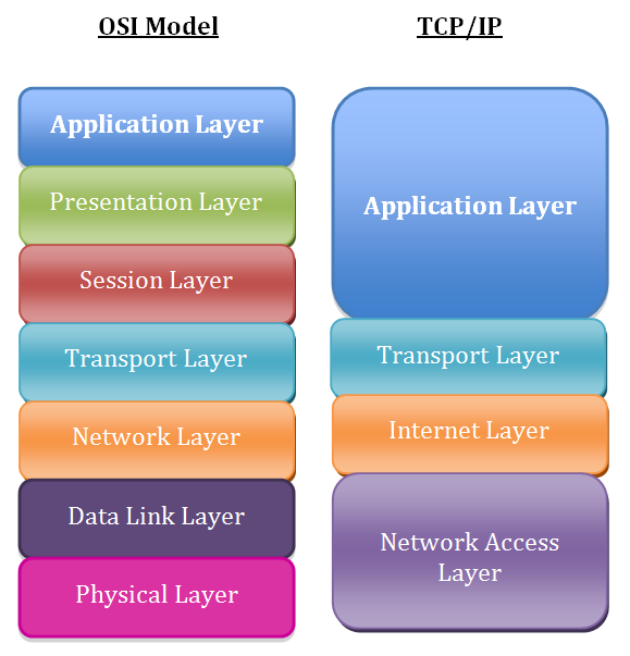
Each layer in these models has a specific job, and it only communicates with the layers directly above and below it. For example, the Physical layer (Layer 1 in OSI) deals with the actual hardware, like cables and radio waves. It doesn't care what the data is, only how to transmit the raw bits. In contrast, the Application layer (Layer 7) works with the software you use, like your web browser or email client. This separation makes it much easier to develop new technologies and troubleshoot problems. If your Wi-Fi isn't working, you can focus on the lower layers without worrying about your browser.
| OSI Layer | Name | TCP/IP Layer | Function |
|---|---|---|---|
| 7 | Application | Application | Provides network services to applications (HTTP, FTP, SMTP) |
| 6 | Presentation | Application | Translates, encrypts, and compresses data |
| 5 | Session | Application | Manages communication sessions between devices |
| 4 | Transport | Transport | Provides reliable or unreliable data delivery (TCP, UDP) |
| 3 | Network | Internet | Moves packets across networks and determines the best path (IP) |
| 2 | Data Link | Network Access | Handles error detection and frames data for a specific network |
| 1 | Physical | Network Access | Transmits raw bits over a physical medium (cables, Wi-Fi) |
IP Addressing and Subnetting
Every device on a network needs a unique address, just like every house on a street needs a mailing address. In TCP/IP networks, this is the IP (Internet Protocol) address. An IPv4 address, the most common type, looks like this: 192.168.1.10.
This address is actually two parts in one: the network ID and the host ID. The network ID is like the street name, identifying which network the device is on. The host ID is like the house number, identifying the specific device on that network. A device called a subnet mask, like 255.255.255.0, is used to tell computers which part of the IP address is the network ID and which is the host ID.
An IP address tells you who a device is, and the subnet mask tells you where it is.
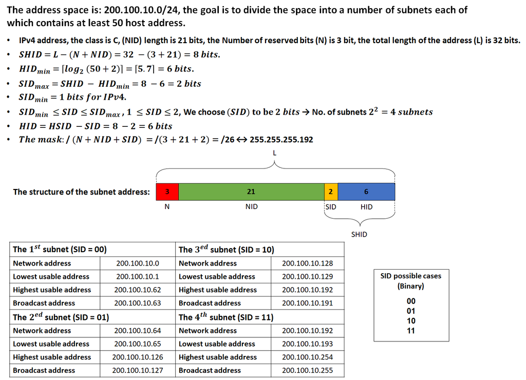
Sometimes, a single large network is too inefficient. Imagine a city with only one giant street. It would be chaotic. Instead, we divide cities into smaller neighborhoods. In networking, this process is called subnetting. We take a large network and break it into smaller, more manageable subnetworks, or "subnets." This improves performance, security, and organization. Subnetting involves borrowing bits from the host portion of the address to create new network portions, allowing for many smaller networks within the original block.
Network Topologies
A network topology is the arrangement of the elements of a communication network. It's the
A network topology is the arrangement of the elements of a communication network. It's the "shape" of the network. Topologies can be physical, describing the actual layout of cables and devices, or logical, describing how data flows between devices.
The most common physical topologies are Bus, Ring, Star, and Mesh.
In a star topology, which is very common in modern networks, all devices connect to a central device. If one cable fails, only one device loses connection. In a mesh topology, devices are interconnected, offering high reliability. If one path fails, data can simply take another route. This is how the internet itself is structured.
Common Network Devices
Several key pieces of hardware make networks function. While you might have a single box at home that does everything, in a business environment, these roles are handled by specialized devices.
switch
noun
A device that connects multiple devices together on a single computer network. It uses MAC addresses to forward data to the correct destination device.
A switch operates at the Data Link layer (Layer 2) and is the foundation of most local networks. It's like a smart traffic cop for a single neighborhood, making sure data packets only go to the intended recipient within that network.
router
noun
A device that connects different networks together and directs traffic between them. It uses IP addresses to determine the best path for data to travel.
A router operates at the Network layer (Layer 3). If a switch is the traffic cop for a neighborhood, a router is the postal service for the entire city. It connects different networks (like your home network and the internet) and figures out the most efficient route for data to travel from its source to its destination.
Understanding these core components—the models that describe communication, the addresses that identify devices, the topologies that define the layout, and the hardware that directs traffic—is the first step to mastering networking.
Now, let's test your knowledge on these foundational concepts.
What is the primary conceptual model that the modern internet is built upon?
In the context of an IP address like 192.168.1.10, what is the purpose of a subnet mask like 255.255.255.0?
With these fundamentals in place, you're ready to start exploring how to configure and manage these devices in a real-world setting.