Centrifugal Pump Mechanics and Applications
Impeller Energy Transfer
From Rotation to Flow
The heart of a centrifugal pump is the impeller, a rotor with curved blades. Its job is to take the rotational energy from a motor and transfer it into a moving fluid. As the motor spins the shaft, the impeller spins with it. This rotation slings the fluid outwards from the center, or 'eye,' of the impeller towards its outer edge.
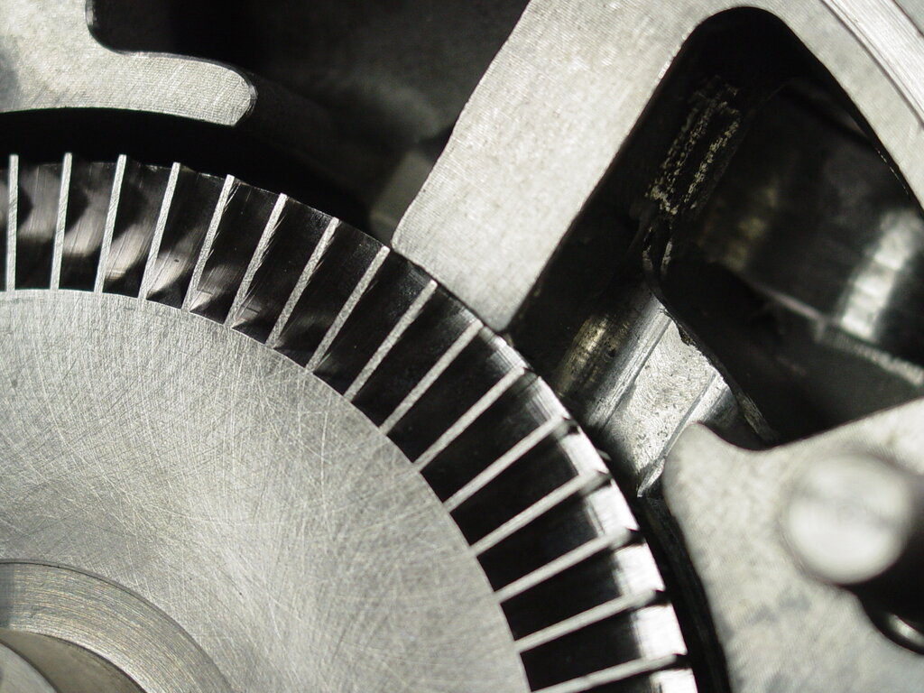
This outward motion is a direct application of centrifugal force. The fluid, forced to follow the curved path of the impeller vanes, rapidly accelerates. This acceleration adds kinetic energy to the fluid, increasing its velocity. The geometry of the impeller vanes is crucial; their shape is carefully designed to guide the fluid smoothly and efficiently, maximizing this energy transfer.
Mapping the Fluid's Path
To understand exactly how energy is transferred, engineers use a tool called a velocity triangles. This is a vector diagram that breaks down the fluid's velocity at both the inlet (where it enters the impeller) and the outlet (where it leaves). It helps visualize three key components of velocity:
| Velocity Component | Symbol | Description |
|---|---|---|
| Absolute Velocity | The fluid's actual velocity relative to the stationary pump casing. | |
| Relative Velocity | The fluid's velocity as it flows along the impeller blade, relative to the moving blade itself. | |
| Blade Velocity | The tangential speed of the impeller blade at a specific point. |
By combining these three vectors, we can see the full picture of the fluid's motion. The absolute velocity () is the vector sum of the relative velocity () and the blade velocity (). We can further break down the absolute velocity into two useful parts: a radial component (), which points directly away from the center of rotation, and a tangential component (), which is parallel to the direction of the blade's motion.
The Energy Equation
The relationship between the impeller's rotation and the energy it imparts to the fluid is captured by a foundational formula in fluid dynamics. The Euler's Pump Equation, developed by the brilliant mathematician in the 18th century, provides the theoretical head (energy per unit weight of fluid) that a pump can deliver.
This equation shows that the energy transfer is directly proportional to the change in the product of the blade speed and the tangential velocity of the fluid as it passes through the impeller. In many pump designs, the fluid enters the impeller eye with very little rotation, so the inlet tangential velocity () is close to zero. This simplifies the equation, making the outlet conditions the primary driver of the pump's head.
The key to energy transfer in a centrifugal pump is increasing the fluid's tangential velocity. The impeller's job is to take in fluid with low rotational speed and eject it at a high rotational speed.
In a real-world pump, the actual head produced will be lower than the theoretical value from Euler's equation. This is due to factors like friction within the pump casing and turbulence created by the fluid flow. However, the equation provides a vital theoretical maximum and a clear understanding of the physics at play.
What is the primary function of the impeller in a centrifugal pump?
A velocity triangle is a tool used by engineers to do what?