Building an Operating System
Bootloader Development
The First 512 Bytes
When you press the power button on a computer, it doesn't magically load your operating system. The first piece of software to run is the , or Basic Input/Output System. Stored on a chip on the motherboard, its job is to initialize the hardware and then find something to boot. The BIOS scans storage devices like hard drives and floppy disks, looking for a very specific pattern: a special 16-bit number, 0xAA55, located at the very end of the disk's first 512-byte sector. This is the boot signature. If the BIOS finds this signature, it assumes the device is bootable. It then copies that entire 512-byte sector into memory at the physical address 0x7C00 and instructs the CPU to start executing the code it just loaded. That tiny 512-byte program is our bootloader.
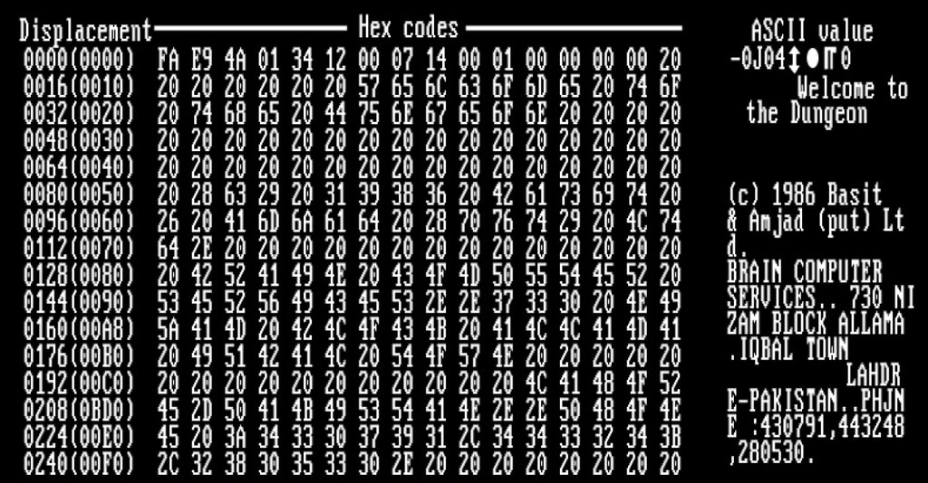
This 512-byte limit is a strict constraint. Our initial code, known as the 'Stage 1' bootloader, must fit entirely within this space, including the boot signature. Its primary job is simple but crucial: load a larger, more capable program (our 'Stage 2' loader or kernel) from the disk into memory.
Waking Up in Real Mode
The CPU starts in a 16-bit environment called . In this mode, memory isn't accessed with a single, straightforward address. Instead, it uses a system called segmented memory. An address is formed by combining a 16-bit segment value with a 16-bit offset. The physical address is calculated as: . Since multiplying by 16 is the same as a bitwise shift left by 4, this is often written as . This scheme allowed 16-bit registers to address 1 MB of memory ( bytes). The CPU has several segment registers: CS (Code Segment), DS (Data Segment), ES (Extra Segment), and SS (Stack Segment). When our bootloader begins at 0x7C00, the BIOS has already set CS to 0x0000 and the instruction pointer IP to 0x7C00, but other segment registers can be unpredictable. A good first step is to normalize them, for instance by setting DS and ES to 0.
Before we can call functions or use the stack, we must set it up. The stack is a region of memory used for storing temporary data, like return addresses when a function is called. We define the stack by loading the SS register with the segment of our desired stack area and the SP (Stack Pointer) register with an offset. The stack grows downwards in memory, so we typically point SP to the top of the allocated stack region.
; Example of setting up segments and stack
org 0x7C00      ; Tell assembler our code is loaded at this address

mov ax, 0       ; Can't move 0 directly into DS
mov ds, ax      ; Set Data Segment to 0
mov es, ax      ; Set Extra Segment to 0

mov ss, ax      ; Stack Segment at 0
mov sp, 0x7C00  ; Stack Pointer starts just below our code
Talking to the BIOS
Our bootloader can't do everything from scratch. It relies on services provided by the BIOS, which are accessed through interrupts. An interrupt is a signal to the CPU to pause its current task and run a special function, called an Interrupt Service Routine (ISR). To call one, we load specific values into CPU registers to tell the BIOS what we want, and then execute the int instruction.
For example, to print a character to the screen, we use BIOS interrupt 10h. The specific function for 'Teletype output' is 0x0E, which is placed in the AH register. The character to print goes in the AL register.
; Print the character 'H'
mov ah, 0x0E    ; Function 0Eh: Teletype output
mov al, 'H'     ; Character to print
int 0x10        ; Video services interrupt
The most important service for our bootloader is reading from the disk. This is done with interrupt 13h. To use it, we need to specify several parameters:
ah = 0x02: The function for reading disk sectors.al: The number of sectors to read.ch: The cylinder number.cl: The sector number to start from (sectors are 1-indexed).dh: The head number.dl: The drive number (e.g.,0x00for the first floppy,0x80for the first hard disk).es:bx: The memory address (Segment:Offset) where the loaded data should be stored.
If
int 13hfails, the carry flag (CF) will be set, and theAHregister will contain an error code. It's crucial to check this flag to handle potential disk read errors.
Putting It All Together
Now we can write a complete Stage 1 bootloader. Its goals are:
- Set up the segment registers and stack.
- Print a message to the screen to show it's running.
- Use
int 13hto load our 'Stage 2' from the disk into a new memory location (e.g.,0x8000). - Jump to the newly loaded code.
Finally, we must ensure the total compiled code is padded to 512 bytes and ends with the 0xAA55 signature. The times and dw directives in NASM are perfect for this.
; A minimal Stage 1 Bootloader
org 0x7C00

mov bp, 0x8000      ; Set up stack base pointer
mov sp, bp          ; Set up stack pointer

mov bx, HELLO_MSG   ; Load address of message
call print_string   ; Call our string printing function

; ... code to load Stage 2 using int 13h would go here ...

jmp $ ; Infinite loop for now

; Function to print a string
print_string:
    mov ah, 0x0E
.loop:
    mov al, [bx]
    cmp al, 0
    je .done
    int 0x10
    inc bx
    jmp .loop
.done:
    ret

HELLO_MSG: db 'Bootloader running...', 0

; Pad to 510 bytes, then add the boot signature
times 510-($-$$) db 0
dw 0xAA55
This simple program establishes a foundation. It takes control from the BIOS, prepares a basic execution environment, and has the logic needed to load the next, more complex part of our operating system. With this step complete, we are no longer just running on bare metal; we are beginning to build a system.