Architectures of Optical Computing
Silicon Photonics Integration
Merging Light and Electronics
For decades, the speed of computers has been dictated by electrons moving through copper wires. But as chips get denser and faster, copper is hitting its physical limits. The wires generate too much heat and consume too much power. The solution? Replacing electrons with photons, the particles of light.
With silicon photonics, photons are generated on, and travel through, “circuits” etched onto silicon chips, enabling conventional chip manufacturing to construct optical parts.
This field, silicon photonics, isn't about building computers entirely out of light. It's about integrating optical components directly onto the same silicon chips that house our electronic circuits. This allows us to use light for what it does best, moving massive amounts of data quickly and efficiently, while using electrons for what they do best, computation.
The Perfect Platform
The backbone of this technology is a special type of wafer called Silicon-on-Insulator (SOI). A standard silicon wafer is just a slice of pure silicon. An SOI wafer is more like a sandwich. It has a thick base of silicon, a thin middle layer of insulating silicon dioxide (), and a very thin top layer of pure silicon.
This structure is ideal for guiding light. The top silicon layer has a high refractive index, while the silicon dioxide layer below it has a much lower one. This difference in refractive index traps light inside the thin silicon layer, turning it into a microscopic waveguide, much like a flat fiber optic cable. Because this is all built using standard silicon manufacturing techniques, it's incredibly scalable and cost-effective.
Integration Strategies
So, we have a platform for both electronics and photonics. How do we combine them? There are two main approaches: monolithic and heterogeneous integration.
Monolithic integration builds everything, both optical and electronic components, on a single silicon chip from the ground up. Think of it as building a house where the plumbing, electrical, and structure are all created simultaneously as one unified system.
Heterogeneous integration fabricates the electronic and photonic components on separate, specialized wafers and then bonds them together. This is like building prefabricated modules, a kitchen and a bedroom, and then assembling them on-site.
| Feature | Monolithic Integration | Heterogeneous Integration |
|---|---|---|
| Performance | Highest potential, shortest connections | Very high, but with potential loss at interfaces |
| Complexity | Extremely high, complex fabrication | Simpler fabrication, complex packaging |
| Materials | Limited to CMOS-compatible materials | Can use the best material for each function |
| Cost & Yield | Higher risk, lower initial yield | Potentially cheaper, can test chips before bonding |
| Best For | Ultra-dense, high-performance systems | Applications needing specialized components (e.g., lasers) |
The choice depends on the application. Monolithic integration promises the ultimate in performance and density, but it's difficult because the optimal processes for creating a good transistor aren't the same as those for a good waveguide. Heterogeneous integration is more flexible, allowing designers to use exotic materials like for light sources, which are far more efficient than pure silicon, and then bond them to a standard CMOS logic chip.
Getting Light On and Off the Chip
A major practical challenge is getting light from an external fiber optic cable, which has a core of about 10 micrometers, into a silicon waveguide that's less than half a micrometer wide. This is like trying to thread a garden hose into the eye of a needle. Two clever solutions exist: edge couplers and grating couplers.
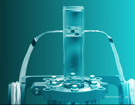
Edge couplers work by carefully shaping the end of the silicon waveguide into a tiny funnel or 'taper'. This taper gradually shrinks the light's mode size from that of the fiber down to the waveguide's size. This method is very efficient and works across a broad range of light wavelengths, but it requires extremely precise alignment and polishing of the chip's edge.
Grating couplers are different. They don't require access to the chip's edge. Instead, they are a series of periodic grooves etched directly into the top of the silicon waveguide. These grooves act like a diffraction grating. When light from a fiber hits the grating from above at a specific angle, the grating diffracts the light and funnels it sideways into the waveguide. While less efficient than edge couplers and sensitive to specific wavelengths, they have a huge advantage: they can be placed anywhere on the chip, making wafer-scale testing much easier.
Even with perfect coupling, light traveling through a silicon waveguide isn't lossless. The primary cause of loss is from scattering. Because the light is so tightly confined, any tiny imperfection or roughness on the sidewalls of the waveguide, a byproduct of the etching process, can scatter photons out of the path, weakening the signal. Minimizing this sidewall roughness is a major focus of fabrication research.
What is the primary limitation of using copper wires for data transfer in increasingly dense and fast computer chips?
How does a Silicon-on-Insulator (SOI) wafer guide light?