Architectural Highlighting and Documentation Techniques
Identifying Structural Framework
Finding the Skeleton
Architectural plans are more than just layouts; they're roadmaps that show how a building stands up. The key is to find the structure's skeleton—the system of components that channels all the weight from the roof down into the ground. This critical network is what separates a stable building from a pile of rubble.
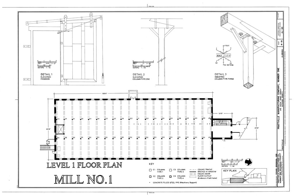
Your first task when looking at a floor plan is to differentiate between the walls that do the heavy lifting and those that just divide space. Load-bearing walls are the primary structural supports, while non-load-bearing walls, or partitions, are simply there to create rooms. On a blueprint, line thickness is your best clue. Exterior walls and thick interior walls are almost always load-bearing. Thinner lines usually indicate partitions.
| Feature | Load-Bearing Wall | Non-Load-Bearing Wall (Partition) |
|---|---|---|
| Primary Function | Supports vertical load from above | Divides interior space |
| Typical Line Weight | Thick, solid lines | Thinner, lighter lines |
| Common Materials | Reinforced concrete, masonry, structural steel | Drywall, wood studs, glass |
| Structural Impact | Critical for building integrity | Can often be moved or removed |
Look for walls that run continuously through the building, especially those aligned with foundation walls or large beams shown on other plan sheets. If a wall on the second floor sits directly on top of a wall on the first floor, it’s a strong candidate for being load-bearing.
Columns and Load Paths
Columns are another core component of the structural skeleton. They appear as solid squares, circles, or other shapes on a plan. Their purpose is to transfer loads from beams and girders down to the foundation. You'll often see them arranged in a regular grid, called a column bay, which creates an efficient system for distributing weight across the building's footprint.
To truly understand a plan, you must trace the load path—the journey that weight takes through the structure. It starts at the roof, travels through joists to beams, then to columns or load-bearing walls, down through the floors, into the foundation, and finally dissipates into the soil. Each connection in this chain must be strong enough to handle the accumulated forces from above.
This path is why a seemingly minor change, like removing a small wall on the first floor, can have catastrophic consequences if that wall is part of the primary load path.
Decoding Structural Symbols
To trace the load path accurately, you need to speak the language of blueprints. Structural symbols are a shorthand that tells you the material and type of component you're looking at. While there are many variations, some patterns are common.
Concrete is often shown with a stippled pattern or diagonal hatching, while steel components, like I-beams, are drawn with their distinctive cross-sectional shape.
For example, a solid black square might represent a concrete column, whereas an 'H' shape represents a steel column. A double line could signify a reinforced concrete beam. These symbols are usually defined in the drawing's legend, but recognizing them at a glance will speed up your analysis. Understanding them allows you to see not just the layout, but the underlying structural strategy.
Loads follow predictable paths: Floors → Beams, Beams → Columns or Walls, Columns/Walls → Foundations, Foundations → Soil
Now, let's test your ability to spot these critical components.
What is the primary purpose of a load-bearing wall?
On a typical blueprint, thicker lines are generally used to indicate load-bearing walls, while thinner lines represent non-load-bearing partitions.
Being able to identify a building's skeleton on a 2D plan is a fundamental skill. It moves you from simply seeing rooms to understanding the forces that hold them together.