Applied Electrical and Electronic Systems
Complex Network Theorems
Beyond Ohm's Law
As circuits grow from simple loops into complex networks, Ohm's law and basic series/parallel rules become cumbersome. Real-world systems, like power grids or the motherboard in your computer, feature multiple power sources and interconnected loops. Analyzing these requires more powerful tools.
Two of the most useful are Thevenin's and Norton's theorems. They allow us to take any complicated linear circuit, no matter how many components it has, and replace it with a simple, predictable equivalent. This is like summarizing a long, rambling story into a single, clear sentence.
Thevenin's theorem states that any two-terminal linear network can be replaced by an ideal voltage source () in series with a resistor (). Norton's theorem is the dual: the same network can be replaced by an ideal current source () in parallel with a resistor (). The key is that and are identical, and the sources are related by Ohm's law: .
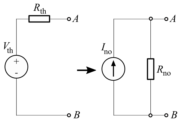
To find the Thevenin equivalent, you determine two things: the open-circuit voltage across the terminals (this is ) and the equivalent resistance looking back into the terminals with all independent sources turned off (this is ). Turning off a voltage source means replacing it with a short circuit, while a current source is replaced with an open circuit. This process transforms a section of a circuit into a simple, predictable block.
Maximum Power Transfer
Simplifying a circuit with Thevenin's theorem is incredibly useful for one specific, common problem: getting the most power out of a source. The states that a source delivers the maximum possible power to a load when the load's resistance () is exactly equal to the Thevenin resistance () of the source network.
This principle is why audio engineers match the impedance of speakers to amplifiers. If an amplifier has an output impedance (its Thevenin resistance) of 8 ohms, it will deliver the most power to an 8-ohm speaker.
However, maximum power does not mean maximum efficiency. When , exactly half the power is dissipated as heat in the source's own internal resistance. For power transmission grids, the goal is high efficiency, not maximum power transfer, so the load resistance is made much larger than the source resistance.
Systematic Analysis Methods
For circuits with multiple loops and sources, a systematic approach is needed to solve for all voltages and currents. Two primary methods exist: Nodal Analysis and Mesh Analysis.
Nodal analysis focuses on the voltages at each principal node (a point where three or more components meet), while Mesh analysis focuses on the currents flowing in each independent loop.
Nodal analysis is generally easier when a circuit has more voltage sources than current sources. It uses Kirchhoff's Current Law (KCL), which states that the sum of currents entering a node must equal zero. By defining one node as a reference (ground, 0V) and writing KCL equations for the other principal nodes, you create a system of equations that can be solved for each node voltage.
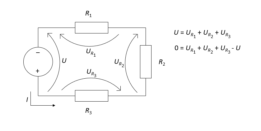
Mesh analysis is the counterpart, best suited for circuits with many current sources or a planar layout (no wires crossing). It uses Kirchhoff's Voltage Law (KVL), which states the sum of voltage drops around any closed loop must equal zero. You assign a mesh current to each closed loop and write KVL equations for each, resulting in a system of equations that solves for the loop currents.
Handling Multiple Sources
What if a circuit has multiple independent sources, like a battery and a solar panel charging it? The Superposition Theorem provides a way to simplify this problem. It states that the total current or voltage in any part of a linear circuit is the sum of the currents or voltages produced by each source acting alone.
To apply superposition, you turn off all but one source, analyze the circuit, and record the result. You repeat this for every source. The final answer is the algebraic sum of the individual results.
Finally, some resistor networks can't be simplified with standard series/parallel rules. Networks in a delta () or pi () configuration can be converted into an equivalent wye () or tee () network. This Delta-Wye transformation can sometimes unlock a circuit, making it solvable with simpler methods. It's a specialized but powerful tool for reconfiguring complex resistor arrangements.
Let's check your understanding of these advanced tools.
Thevenin's theorem simplifies a complex linear circuit into what equivalent form?
When analyzing a circuit to find its Thevenin resistance (), how should independent sources be handled?