Agricultural Engineering Semester 1 Exam Mastery
Farm Power Mechanics
Engine Cycles and Operation
The heart of modern agricultural machinery is the internal combustion (IC) engine. Understanding its operation isn't just about knowing the parts; it's about grasping the precise, timed sequence of events that convert fuel into work. The most common type found in tractors is the four-stroke engine, which completes a power cycle in four piston strokes: intake, compression, power, and exhaust.
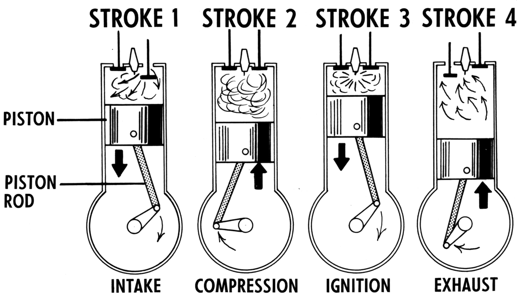
A less common but simpler alternative is the two-stroke engine. It combines the intake and compression strokes into one upward movement of the piston, and the power and exhaust strokes into one downward movement. This design eliminates the need for valves, using ports in the cylinder wall instead. While lighter and offering a higher power-to-weight ratio, two-stroke engines are generally less fuel-efficient and produce more emissions, relegating them to smaller equipment like chainsaws or leaf blowers rather than large tractors.
Perfecting the Rhythm
For an engine to run efficiently, the intake and exhaust valves must open and close at precisely the right moments relative to the piston's position. This coordination is visualized in a valve timing diagram. The diagram is a circle representing the 360° rotation of the crankshaft for two full revolutions (720° in a four-stroke cycle). Key positions are Top Dead Centre (TDC), the piston's highest point, and Bottom Dead Centre (BDC), its lowest point.
Notice that the valves don't open and close exactly at TDC or BDC. The intake valve opens slightly before TDC to allow the fuel-air mixture to start entering early, taking advantage of its momentum. This is called valve lead. The valve then closes after BDC, known as valve lag, to pack as much mixture into the cylinder as possible.
Similarly, the exhaust valve opens before BDC to allow the high-pressure exhaust gases to start escaping, reducing the work the piston must do on the exhaust stroke. It closes after TDC to ensure all spent gases are cleared out. These subtle overlaps are critical for maximising engine power and efficiency at high speeds.
Measuring Engine Performance
To evaluate and compare engines, engineers use several key metrics. The most fundamental are displacement and compression ratio. Displacement is the total volume swept by all the pistons in the engine. It's a direct indicator of the engine's size.
The compression ratio is the ratio of the total cylinder volume (at BDC) to the clearance volume (the small space left at TDC). A higher compression ratio generally leads to higher thermal efficiency, but it also increases stress on engine components.
Beyond physical dimensions, we measure the power an engine produces. The theoretical power developed inside the cylinder from fuel combustion is called Indicated Power (). However, some of this power is lost to friction between moving parts like pistons, bearings, and gears. The actual, usable power delivered at the crankshaft is called Brake Power ().
This is often measured using a brake dynamometer and is the figure manufacturers quote. Brake power is typically expressed in kilowatts (kW) or, more traditionally, Brake Horsepower (BHP).
The relationship between these two power figures gives us the Mechanical Efficiency (") of the engine, which is simply the ratio of brake power to indicated power. A higher mechanical efficiency means less power is being lost to internal friction.
Another crucial metric is Thermal Efficiency (" ). It measures how effectively the engine converts the chemical energy in the fuel into useful work. No engine is 100% efficient; a large portion of the fuel's energy is lost as waste heat through the exhaust and the cooling system. A typical diesel engine in a tractor might have a thermal efficiency of 35-45%.
To calculate the indicated power without directly measuring it, engineers use a concept called Indicated Mean Effective Pressure (IMEP). This is a fictional, constant pressure that, if applied to the piston throughout the power stroke, would produce the same amount of work as the actual, varying cylinder pressure. It's a useful abstraction for analysis and design.
Finally, all these systems must be managed. For instance, a component called the is crucial for maintaining a constant engine speed under varying loads. When a tractor encounters tougher soil, the load increases and the engine naturally wants to slow down. The governor automatically adjusts the fuel injector to supply more diesel, increasing power to maintain the set speed. Conversely, it reduces fuel when the load lightens.
Now, let's test your understanding of these performance metrics.
What is the correct sequence of strokes in a four-stroke internal combustion engine?
In engine terminology, what is 'valve lag'?
By mastering these concepts, you can analyse and compare the performance of any internal combustion engine, a critical skill in agricultural engineering.