Advanced STM32 Register-Level Systems
Cortex-M Architecture Deep-Dive
The Programmer's Model
To move beyond writing simple C code and start engineering firmware, you need to understand the machine's perspective. For an ARM Cortex-M processor, this starts with the programmer's model, which is essentially the set of registers the CPU uses to do its work.
The core has 16 registers, each 32 bits wide. They are labeled R0 through R15.
| Register | Function | Description |
|---|---|---|
| R0 - R12 | General Purpose | Used for data manipulation, calculations, and temporary storage. R0-R3 are often used to pass arguments to functions. |
| R13 | Stack Pointer (SP) | Points to the top of the current stack in memory. The CPU uses this to push and pop data. |
| R14 | Link Register (LR) | Stores the return address when a function is called. This is how the CPU knows where to go back to. |
| R15 | Program Counter (PC) | Holds the memory address of the next instruction to be executed. It's the engine of program flow. |
While most of these are for general use, the last three have special roles that are critical to how your code runs. Besides these, there are special-purpose registers that manage the processor's state. One of the most important is the Program Status Register (xPSR), which contains flags about the result of the last operation (like was it zero, or did it cause a carry?) and the current execution state.
Thread vs. Handler Mode
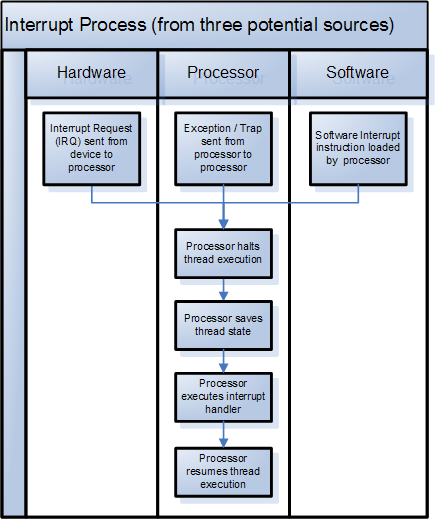
A Cortex-M processor doesn't just run your main loop. It's constantly ready to be interrupted by events, like a timer finishing or data arriving on a communication port. To manage this, the CPU operates in one of two modes: Thread mode or Handler mode.
-
Thread Mode: This is the default state. It's where your main application code runs. The processor is in Thread mode when it's executing the
main()function and any functions called from it. -
Handler Mode: When an exception or interrupt occurs, the processor automatically switches to Handler mode. It executes a dedicated function for that event, called an Interrupt Service Routine (ISR). Once the ISR is complete, the processor returns to Thread mode, picking up exactly where it left off.
Think of it like cooking. Thread mode is you following the recipe. Handler mode is when the oven timer goes off, and you have to stop chopping vegetables to take the bread out. Once that's done, you go back to chopping.
This dual-mode operation is fundamental to real-time systems. It allows the microcontroller to respond to urgent events without derailing the main application logic. The switch between modes is handled entirely by the hardware, making it fast and deterministic.
To control this behavior, the CPU uses two key special registers: PRIMASK and CONTROL. PRIMASK can be used to disable all interrupts (with some exceptions), which is useful for critical sections of code that must not be interrupted. The CONTROL register determines which stack pointer is currently in use and whether the CPU is running in a privileged or unprivileged state.
Managing Stacks and Memory
To support the two execution modes, the Cortex-M architecture features two separate stack pointers. A stack is a region of RAM used for temporary storage, like local variables and the return addresses of functions.
-
Main Stack Pointer (MSP): This is the default stack pointer, used by the operating system kernel and all interrupt service routines (in Handler mode).
-
Process Stack Pointer (PSP): This stack pointer is typically used for application tasks in Thread mode, especially when an RTOS is involved.
Using two separate stacks provides a crucial layer of protection. If an application task overflows its stack (a common bug), it corrupts its own PSP-managed stack but doesn't damage the main stack used by the kernel and interrupt handlers. This prevents a single buggy task from crashing the entire system.
Booting and Exceptions
So how does the processor know where to start? When a Cortex-M device powers on or resets, the hardware doesn't magically jump to your main() function. It follows a precise, hardware-defined sequence.
First, it reads the memory address stored at location 0x00000004. This address points to the start of the reset handler, which is the first piece of code to run. This location is part of the Vector Table, a list of memory addresses that tell the CPU where to find the handlers for every possible system exception, including reset, interrupts, and faults.
The reset handler's job is to initialize the system. This typically includes setting up the clock, initializing memory (like copying initial values for global variables from Flash to SRAM), and finally, calling your main() function. Only then does your application code begin to execute.
This entire process relies on the exception model. Every interrupt is assigned a priority level. If a low-priority interrupt is running and a high-priority one occurs, the processor will pause the current ISR, save its state, and immediately begin executing the higher-priority ISR. This concept, known as nested interrupts, is crucial for building responsive and reliable embedded systems that can handle multiple events concurrently.
Let's check your understanding of these core concepts.
What is the primary difference between Thread mode and Handler mode on a Cortex-M processor?
Immediately after a reset, what is the first action a Cortex-M processor performs to start executing code?
Understanding this architecture is the key to unlocking the full power of STM32 microcontrollers. It's the difference between merely using library functions and truly engineering a robust, efficient firmware solution.