Advanced Schematic Design and Analysis
Standardized Symbol Libraries
Speaking a Common Language
Imagine trying to build a complex machine with instructions written in a dozen different languages. It would be chaotic. Electronic schematics are the instructions for circuits, and to avoid chaos, engineers rely on standardized symbol libraries. These libraries ensure that a resistor in a schematic designed in Germany looks the same as one in a schematic from Japan or the United States.
The two dominant standards are the IEC 60617, maintained by the International Electrotechnical Commission, and the ANSI/IEEE 315, from the American National Standards Institute and the Institute of Electrical and Electronics Engineers. While largely similar, they have key differences. IEC 60617 is prevalent in Europe and Asia, while ANSI/IEEE 315 is the standard in North America. Knowing the difference is crucial for creating universally understood documentation.
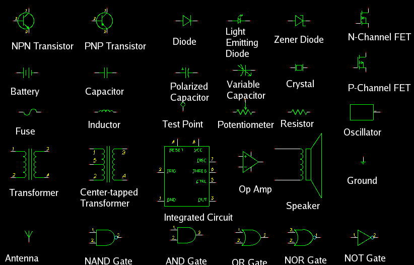
The most common difference you'll encounter is the resistor. The IEC standard uses a simple rectangle, while the ANSI standard uses a zigzag line. Neither is better, but consistency is key. If you're working on a project for a European client, use the IEC rectangle. For a U.S.-based project, the zigzag is expected.
| Component | IEC 60617 Symbol | ANSI/IEEE 315 Symbol |
|---|---|---|
| Resistor | Rectangle | Zigzag Line |
| Potentiometer | Rectangle with arrow through it | Zigzag with arrow through it |
| Capacitor (non-polarized) | Two parallel lines | One straight, one curved line |
| Inductor | Filled-in rectangle or loops | Coiled line |
Active and Complex Components
The differences extend beyond simple passive components. Active components like transistors and logic gates also have distinct visual styles. For example, logic gates in the ANSI standard often have unique shapes (like the D-shape for an AND gate), whereas the IEC standard prefers uniform rectangles with a symbol inside to denote the function.
For complex parts like integrated circuits (ICs), schematics rarely draw the internal logic. Instead, they use a simple rectangle with pins. The key is how these pins are organized. A physical layout shows the pins as they appear on the actual chip. A logical layout groups pins by function (e.g., all data bus pins together, all address pins together), making the schematic easier to read and understand. Both are valid, but the logical layout is usually preferred for clarity in the design phase.
Labels and Values
Symbols are only half the story. The labels attached to them provide critical information. Every component gets a Reference Designator (REFDES), like R1, C1, or U1. This is a unique identifier for that specific component on the board. The 'R' denotes a resistor, 'C' a capacitor, and 'U' an integrated circuit. This system creates a one-to-one mapping between the schematic and the physical printed circuit board (PCB).
For example, if the schematic shows a 10kΩ resistor labeled R7, you can find the exact location of that component on the PCB by looking for the R7 silkscreen marking.
Component values also follow a standard format. To avoid ambiguity with decimal points, unit prefixes are often used in their place. For instance, a 4,700 Ohm resistor might be written as 4k7 instead of 4.7k. A 2.2 microfarad capacitor could be 2µ2. This convention prevents errors that could arise from a poorly printed or hard-to-read decimal point.
By adhering to these standards for symbols, reference designators, and value notation, you create professional schematics that are clear, unambiguous, and easily understood by engineers anywhere in the world.
What are the two dominant international standards for electronic schematic symbols?
In a schematic created in North America, a resistor is most likely represented by a ______.