Advanced Marine Networking and AIS Sales
NMEA 2000 Architecture
From Serial Wires to a Network Bus
In the world of marine electronics, NMEA 0183 was the standard for decades. It worked, but it was a one-to-one system. A single device, called a "talker," would send data to one or more "listeners." If you wanted two devices to communicate, you had to wire them directly together. A boat with a GPS, an autopilot, and a chartplotter quickly became a rat's nest of dedicated wires. Each new device added more complexity.
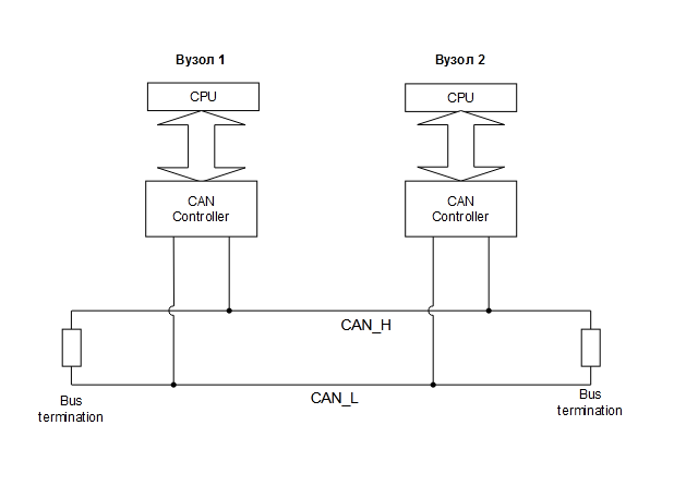
NMEA 2000, often called N2K, changed all that by moving to a network model. Instead of direct point-to-point connections, all devices connect to a common data highway. This system is built on a robust technology originally developed for the automotive industry called the CAN bus. It allows any device to talk to any other device on the network, making installations simpler and more powerful. One device can broadcast its data, and multiple other devices can receive and use it simultaneously without any extra wiring.
The N2K Physical Network
An NMEA 2000 network has a specific physical layout, often called a trunk-and-drop or backbone topology. It’s not a free-for-all where you can connect cables however you like. Getting the physical layer right is the first step to a stable network.
The key components are:
- Backbone (or Trunk): The main data and power channel. It runs through the vessel, typically made of thicker cabling.
- Terminators: A 120-ohm resistor is required at each end of the backbone. Without them, signals will reflect back down the cable, causing data errors. Every N2K network must have exactly two.
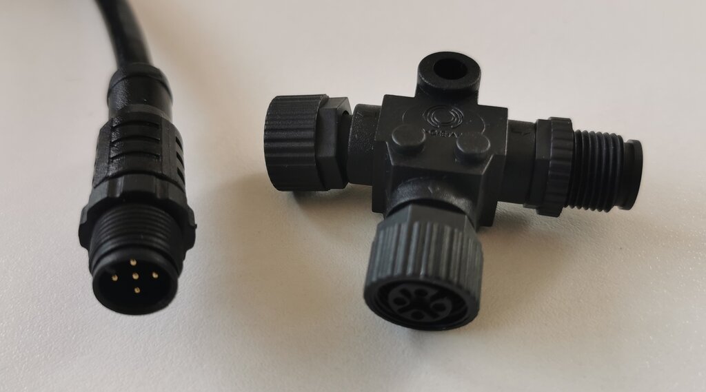
- T-Connectors: These connect drop cables to the backbone.
- Drop Cables: Shorter, usually thinner cables that connect an individual device to a T-connector on the backbone.
- Power Insertion Point: A dedicated T-connector where 12V DC power is supplied to the entire network.
N2K Design Rules
To ensure data integrity and sufficient power for all devices, NMEA 2000 networks must adhere to strict length and device count limitations. Breaking these rules is the most common source of intermittent problems and device dropouts.
The three golden rules are: a maximum backbone length, a maximum drop cable length, and a maximum number of devices.
First, the maximum number of physical devices on a single N2K network is 50. While this is a hard limit, you will likely run into power limitations long before you reach 50 devices.
Second, individual drop cables cannot exceed 6 meters (20 feet). Longer drops can cause signal reflections and degrade the network. There's no minimum length, but you can't daisy-chain drop cables to make them longer.
Finally, the total length of the backbone is critical, and it depends on the type of cable you use. Most smaller installations use "Micro" or "Light" cable, while larger vessels require heavier "Mini" or "Heavy" cable to carry power over longer distances without excessive voltage drop.
| Cable Type | Max Backbone Length | Max Cumulative Drop Length | Max Current |
|---|---|---|---|
| Micro/Light | 100 meters (328 ft) | 78 meters (256 ft) | 3 Amps |
| Mini/Heavy | 250 meters (820 ft) | 78 meters (256 ft) | 8 Amps |
Calculating Network Load
Every NMEA 2000 certified device has a (LEN) specified by the manufacturer. This number represents how much current the device draws from the network. Understanding LEN is essential for designing a network that won't overload its power supply.
To find the total load on your network, you simply add up the LEN values of every device connected to it and multiply by 50mA. For a standard network using Micro-cabling, this total must not exceed 3 Amps (3000 mA).
Let's say you have a network with:
- A chartplotter (LEN 3)
- A GPS antenna (LEN 1)
- A depth sounder (LEN 2)
- An autopilot computer (LEN 4)
A total draw of 500 mA (or 0.5A) is well below the 3A limit for a Micro-cabled backbone, so this network is safe from a power perspective. Exceeding the current limit can cause the power supply fuse to blow or, in less severe cases, lead to low voltage at the ends of the backbone, causing devices to fail intermittently.
Time to check your understanding of N2K architecture.
What is the primary architectural difference between an NMEA 0183 system and an NMEA 2000 system?
Every NMEA 2000 network requires exactly ______ 120-ohm terminators to be installed on its backbone for proper operation.
By following these physical and electrical rules, you can design and build robust NMEA 2000 networks that provide reliable communication between all the marine electronics on a vessel.