Advanced Heat Transfer and Cooling Loads
Complex Thermal Resistances
Beyond Simple Walls
You already know that every material in a building's shell, from insulation to drywall, resists the flow of heat. This property is its R-value. But real walls, roofs, and floors aren't just single, uniform slabs. They're composite assemblies of many different layers.
To accurately model heat loss, we need to think of these assemblies as electrical circuits. Instead of voltage and current, we have temperature difference and heat flow. Each layer, including the thin films of air on the interior and exterior surfaces, acts as a resistor in series. The total thermal resistance is simply the sum of the individual resistances.
The resistance of the air films depends on factors like wind speed and surface orientation. For example, a sheltered exterior wall will have a higher air film resistance than one exposed to high winds. Standardised values are used for typical conditions in load calculations.
Once you have the total resistance, calculating the overall heat transfer coefficient, or , is straightforward. It's the reciprocal of the total R-value. The U-factor tells you how much heat flows through a square metre of the assembly for every degree Celsius of temperature difference.
The Problem of Thermal Bridging
The simple series calculation works perfectly for a uniform, multi-layered wall. But most walls aren't uniform. They contain structural elements like wood or steel studs that interrupt the insulation layer. Heat, like electricity, follows the path of least resistance.
These studs have a much lower R-value than the insulation around them. They act as —highways for heat to bypass the insulation and escape the building. A wall's true performance can be significantly worse than you'd estimate by just looking at the insulation's R-value. Ignoring thermal bridging can lead to undersized HVAC systems and uncomfortable buildings.
To account for this, we must analyse the wall as a combination of series and parallel heat flow paths. Two primary methods are used for this: the Parallel Path method and the Isothermal Planes method.
Calculating Non-Uniform Assemblies
The Parallel Path method is the simpler of the two. It assumes heat flows in straight lines directly through the different sections of the wall. You calculate the U-factor for the insulated cavity section () and the U-factor for the framing section () separately. Then, you create a weighted average based on the area each component occupies.
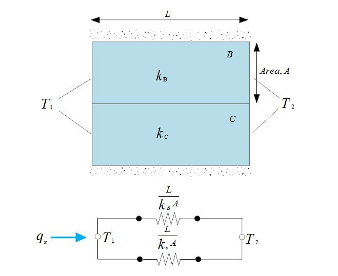
This method is fast but tends to overestimate the wall's performance (underestimate the U-factor) because it ignores the lateral heat flow into the stud from the surrounding insulation.
The Isothermal Planes method is more accurate and generally preferred. It assumes that the surfaces of each material layer are at a uniform temperature (isothermal). This method treats the wall as a network of series and parallel resistances. Layers that are continuous, like drywall or sheathing, are treated as series resistances. Layers that are interrupted, like the stud-and-insulation layer, are treated as parallel resistances.
This approach more accurately reflects how heat moves laterally toward the highly conductive studs, providing a more realistic, and typically higher, U-factor. For professional load calculations under protocols, understanding and applying these detailed methods is essential for designing efficient and effective HVAC systems.
Mastering these calculations allows you to move beyond simple averages and model the true thermal performance of a building envelope, ensuring your designs are both accurate and energy-efficient.