Advanced Hardware Systems Engineering
Advanced Schematic Architecture
From Blueprint to Architecture
Moving beyond basic schematics means thinking like an architect, not just a builder. A professional schematic isn't just a list of connections; it's a high-level plan that communicates the entire system's structure, function, and constraints. The first step is to zoom out and create a system block diagram. This isn't about individual resistors or capacitors. It's about defining the major functional blocks of your design: the power supply, the microcontroller unit (MCU), the sensor interfaces, the communication block, and so on.
This diagram becomes your guide. Before you even place a component symbol, you start making critical decisions. For example, you perform a power budget analysis. You estimate the current draw of each block to size your power supply correctly. Will a simple linear regulator work, or do you need a more efficient switching regulator? This high-level planning prevents costly redesigns later.
Choosing the Brains
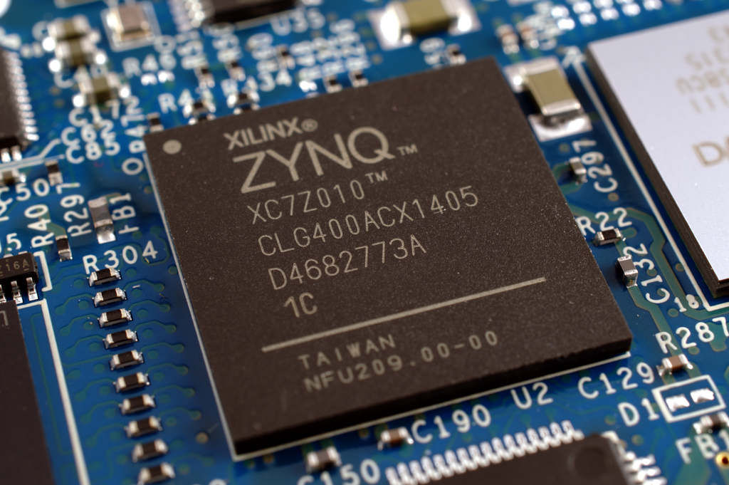
Selecting the central processor is one of the most important decisions. Do you need a microcontroller (MCU) or a more powerful (SoC)? An MCU, like an STM32, integrates a CPU core, RAM, and flash memory on a single chip. It's fantastic for real-time control tasks and power-sensitive applications. An SoC, on the other hand, is a more complete computer system. It typically includes an MCU plus advanced peripherals like a GPU, wireless radios, and memory management units, designed to run a full operating system like Linux.
The choice depends on trade-offs. An SoC offers immense power but comes with higher complexity and power consumption. An MCU is simpler and more energy-efficient but has limited processing capability.
Once you've chosen your processor, the pin-mapping process begins. This isn't just about connecting peripherals randomly. You need a strategy. Tools like ST's STM32CubeMX are invaluable here. They allow you to graphically assign functions like UART, I2C, or SPI to physical pins, and the tool will flag conflicts. A good strategy involves grouping high-speed signals away from sensitive analog inputs and ensuring that peripherals that need to run simultaneously don't share underlying timers or resources.
Guarding the Gates
Production-ready hardware must be robust. Your schematic needs to include protection circuits to shield your delicate components from the harsh realities of the physical world. This goes beyond simple fuses. For any external connection, like a USB port or a sensor input, you must consider electrostatic discharge (ESD) protection. Specialized are placed on these lines to safely shunt dangerous voltage spikes to ground before they can damage your MCU.
Another key element is noise filtering. High-frequency noise from switching power supplies or fast digital signals can disrupt performance. are small passive components that act as high-frequency chokes. Placed in series on a power or signal line, they block unwanted noise while allowing the desired DC or low-frequency signal to pass through. For data lines that travel over cables, you might also use magnetics, like common-mode chokes, to suppress noise picked up from external sources.
Finally, the schematic is where you begin planning for high-speed design. You don't wait for the PCB layout phase. Within your schematic editor, you can define net classes. For example, you can group all the clock signals into a 'clocks' class and all USB data lines into a 'usb_data' class. You can also identify differential pairs, like the D+ and D- lines for USB, and flag them as such. This embeds design intent directly into the schematic. When you import this data into your PCB tool, these constraints are already in place, guiding the layout engineer to treat these critical signals with the special care they require, like controlled impedance routing and length matching.
Now that you've laid out the architectural plan, let's review these advanced concepts before we move on.
Ready to test your knowledge?
What is the primary purpose of creating a system block diagram before starting a detailed schematic?
You are designing a portable, battery-powered sensor that performs a simple, repetitive control task. Which type of processor is generally the more suitable choice?
By treating the schematic as a comprehensive architectural document, you ensure your design is robust, manufacturable, and aligned with its performance goals from the very beginning.