Advanced Electronic Circuit Design
Impedance Matching
The Handshake Problem
Imagine trying to throw a baseball from a moving train to a friend standing on a platform. If you just throw it normally, the ball's speed relative to your friend will be off. The transfer of energy isn't clean. In electronics, a similar problem occurs when an electrical signal moves from one part of a circuit to another, especially at high frequencies.
Every component that generates a signal (a source) has an internal opposition to current flow, and every component that receives a signal (a load) has its own opposition. This total opposition in AC circuits is called impedance. For the most efficient transfer of power from the source to the load, their impedances must match. It's like a perfect handshake between two parts of a circuit.
Impedance
noun
The total opposition that a circuit presents to an alternating current. It includes both resistance and reactance and is measured in ohms (Ω).
When impedances don't match, not all the signal's energy is transferred to the load. Some of it gets reflected back towards the source. This is a big problem in high-frequency systems like radio communications or high-speed digital circuits. Reflected signals can distort the original signal, cause data errors, or even damage components by creating too much voltage in one spot.
Transmission Lines
At high frequencies, even simple wires and PCB traces act as transmission lines. These aren't just simple conductors; they are complex components with their own characteristic impedance (). This value depends on the physical construction of the line, like the width of a copper trace on a circuit board and its distance from a ground plane.
For maximum power transfer and zero reflections, the impedance of the source () must equal the characteristic impedance of the transmission line (), which in turn must equal the impedance of the load ().
Achieving this perfect match is the core goal. Designers carefully control the dimensions of traces on a circuit board to achieve a specific characteristic impedance, often 50 ohms, which is a common standard in RF and high-speed digital systems.
Matching Techniques
What if your load, like an antenna, has an impedance of 75 ohms but your source is 50 ohms? You can't just connect them. You need a circuit in between to make the 50-ohm source think it's connected to a 50-ohm load. This is done with a matching network.
A matching network is a circuit that transforms one impedance value into another, making a mismatched load appear to match the source.
The simplest matching networks are made with inductors (L) and capacitors (C). By arranging these components in specific ways, like an 'L' shape, they can cancel out the reactive parts of an impedance and transform the resistive part. For example, an L-network can make a 100-ohm resistor look like a 50-ohm resistor to the source.
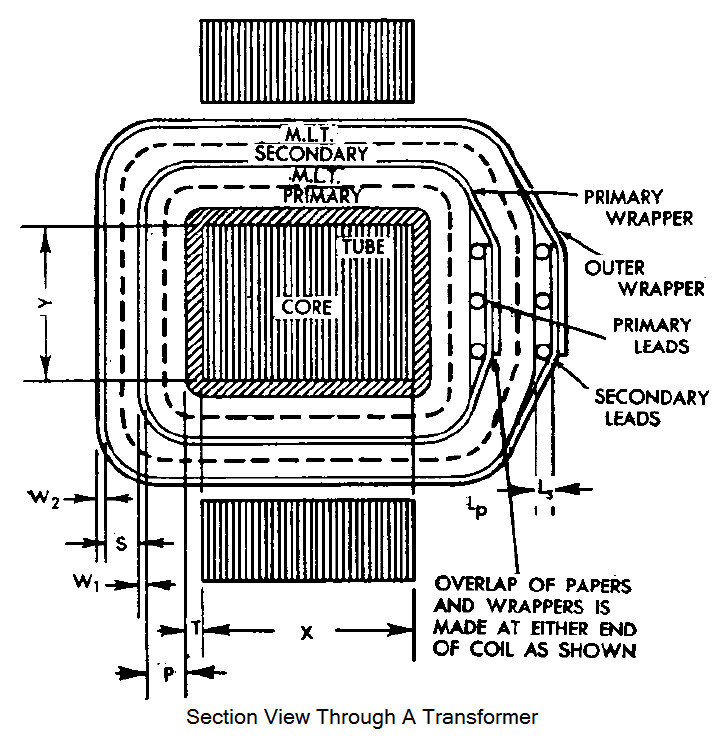
Transformers are another powerful tool. A transformer with a specific ratio of turns in its primary and secondary windings can scale an impedance up or down. This is common in audio systems to match a high-impedance amplifier to a low-impedance speaker, and in radio antennas.
Checking Your Match
Designing a matching network is one thing; making sure it works is another. Engineers use sophisticated software to simulate how signals will behave in a circuit before it's ever built. This allows them to fine-tune the matching network for optimal performance.
Once the circuit is fabricated, it's tested with equipment like a Vector Network Analyzer (VNA). A VNA sends a known signal into the circuit and precisely measures what gets reflected back. The amount of reflection tells the engineer how good the impedance match is. The goal is to get the reflection as close to zero as possible across the desired range of frequencies.
Let's check your understanding of these key concepts.
What is the primary goal of impedance matching in an electronic circuit?
In a high-frequency system, what is the most direct consequence of a mismatch between the source impedance and the load impedance?
Mastering impedance matching is crucial for any high-frequency design. It ensures that the maximum amount of power gets where it needs to go, allowing devices to work efficiently and reliably.