Advanced CANBus Reverse Engineering Techniques
Advanced CANBus Analysis
Beyond the Basics
You understand how a CAN bus works. You can plug in a tool and see messages flying back and forth. But what happens when the messages are a mystery? When the manufacturer hasn't published the specifications, you're left with a stream of hexadecimal numbers that mean... something. This is where advanced analysis begins. It's detective work for digital systems.
The first step is to move beyond simply watching the data. You need to interact with the system. Change a variable and see what happens on the bus. Turn on the headlights, press the brake pedal, or adjust the cabin temperature. Each action will likely trigger a change in the CAN messages. Your job is to capture this traffic and isolate the specific bytes that correlate with the action. This process, often called reverse engineering, relies on careful observation and repetition.
A change in the physical state of the system should correspond to a change in the data on the bus. Isolate the action, then find the corresponding data.
This isn't always straightforward. A single action might change multiple messages, or one message might contain data for several unrelated functions. For example, a single message ID might carry data for both the windshield wiper speed and the turn signal status. Decoding these proprietary formats requires patience and a systematic approach. You'll build a map, one message ID and one data byte at a time, until the raw hex data begins to tell a story.
The Rules of the Road
Every node on a CAN bus can transmit whenever the bus is free. This sounds like a recipe for chaos, but the system has a built-in mechanism to prevent collisions and prioritize information. It's called message arbitration.
When any CAN node is ready to transmit data, it should undergo a process called message arbitration.
Arbitration hinges on the message identifier (ID). The CAN standard specifies that a '0' bit is dominant and a '1' bit is recessive. This means if one node transmits a '0' and another transmits a '1' at the same time, the bus will reflect the '0'.
When multiple nodes start transmitting simultaneously, they also listen to the bus. As they send their message ID, bit by bit, they compare what they sent to what's actually on the bus. If a node sends a recessive '1' but sees a dominant '0', it knows it has lost arbitration. It immediately stops transmitting and waits for the bus to become free again. The node that sent the '0' continues, unaware there was ever any competition.
The result is that the message with the lowest numerical ID will always win arbitration. This creates an inherent priority system. A message with ID 0x100 will win over a message with ID 0x200. Critical messages, like those for airbag deployment or brake control, are assigned low-numbered IDs to ensure they are never delayed.
Handling Errors
The CAN protocol is robust, with several built-in mechanisms for detecting errors. If a node detects an error—like a bit that doesn't match what it should be or an invalid message format—it immediately transmits an 'Error Frame'.
An Error Frame is a special message that violates the standard bit-stuffing rules of CAN. It consists of six dominant bits in a row, a sequence that every other node on the bus will recognize as an error. Upon detecting an Error Frame, all nodes discard the message that was being transmitted and the original sender attempts to retransmit its message once the bus is free.
Bit Stuffing
noun
A process used in the CAN protocol to ensure synchronization. After five consecutive bits of the same polarity (five 1s or five 0s), the transmitter inserts a complementary bit into the stream. The receiver automatically removes this stuffed bit.
This system is highly effective, but it can also be a source of problems. A single faulty node can continuously detect errors (sometimes incorrectly) and flood the bus with Error Frames, a condition known as a 'babbling idiot'. This can prevent any valid messages from getting through.
To prevent this, CAN controllers have a fault confinement mechanism. Each controller maintains two internal counters: a Transmit Error Counter (TEC) and a Receive Error Counter (REC). These counters increment when errors are transmitted or received and decrement on successful transmissions/receptions. If a counter exceeds a certain threshold, the node enters a different state. If the TEC exceeds 255, the node enters a 'Bus Off' state and removes itself from the network completely, preventing it from disrupting the bus any further.
When analyzing a network, observing frequent Error Frames or a node that repeatedly goes Bus Off can be a key clue. It points you directly to a physical layer problem, a faulty transceiver, or a misconfigured node. Specialized tools, like a logic analyzer or an oscilloscope, can help you diagnose these physical layer issues by visualizing the actual voltages on the bus lines.
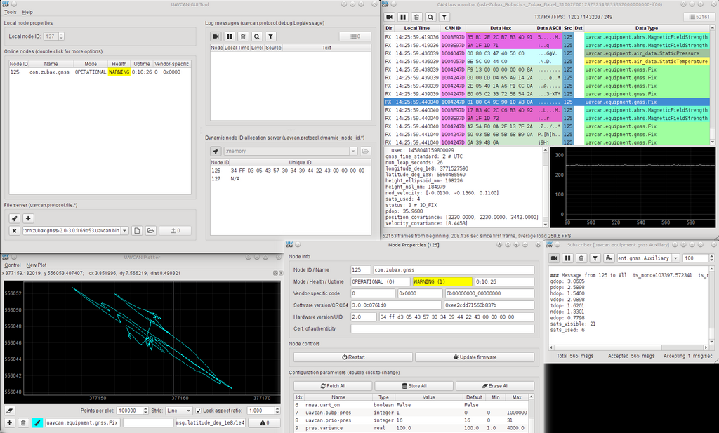
Advanced analysis is about peeling back the layers. You move from the application layer of message payloads down to the data link layer of arbitration and error handling, and finally to the physical layer of voltages and timing. By understanding how these layers interact, you can diagnose complex problems and reverse-engineer even the most opaque systems.
When trying to reverse-engineer a proprietary CAN bus, what is the most effective initial step to identify the message related to the vehicle's headlights?
Four CAN nodes start transmitting their message IDs at the exact same time. Which message will win arbitration and be transmitted successfully?