Active Electronic Components and Symbols
Diodes and Power Rectification
The One-Way Gate
At the heart of a diode is the P-N junction, a boundary between two types of semiconductor material. The P-type material has an abundance of positive charge carriers (holes), while the N-type has an excess of negative charge carriers (electrons). When these two materials meet, electrons from the N-side diffuse across the junction to fill holes on the P-side. This creates a thin, charge-depleted region right at the boundary, known as the depletion region. An internal electric field forms across this region, acting like a small barrier, or a one-way gate, that opposes further charge movement.
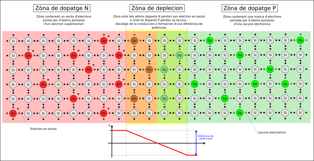
This internal structure gives the diode its fundamental property: it allows current to flow easily in one direction but blocks it in the other. In circuit diagrams, we don't draw the P-N junction. Instead, we use a simple symbol: an arrow pointing to a vertical line. The arrow points in the direction of conventional current flow.
- Anode (+): The flat side of the triangle. This is the P-type side.
- Cathode (-): The vertical line. This is the N-type side.
Forward and Reverse Bias
A diode's behavior depends entirely on how voltage is applied to it. This is known as biasing.
When you apply a positive voltage to the anode and a negative voltage to the cathode, the diode is in forward bias. The external voltage pushes charge carriers toward the junction, overcoming the internal electric field and shrinking the depletion region. Once the applied voltage exceeds the diode's built-in potential (typically around 0.7V for silicon diodes), the gate opens, and current flows freely. This small voltage requirement is called the forward voltage drop.
In forward bias, a diode acts like a closed switch, but with a small voltage cost to turn it on.
If you reverse the polarity, applying a negative voltage to the anode and a positive voltage to the cathode, the diode is in reverse bias. The external voltage pulls charge carriers away from the junction, widening the depletion region and reinforcing the internal barrier. This effectively blocks current flow. Only a tiny, often negligible, leakage current can pass through.

However, if the reverse voltage becomes too high, it can force the junction to break down, causing a large current to flow in the reverse direction. This is called breakdown voltage, and for a standard diode, it's usually a destructive event.
Specialized Diodes
While all diodes share the same basic principle, some are designed to exploit specific characteristics for specialized tasks.
Zener Diode
noun
A diode designed to operate reliably in the reverse breakdown region.
Unlike a standard diode, a Zener diode is engineered to have a precise and non-destructive breakdown voltage, called the Zener voltage (). When reverse-biased to this specific voltage, it allows current to flow while keeping the voltage across it constant. This makes it incredibly useful for voltage regulation, acting as a clamp that prevents a circuit's voltage from exceeding a certain level.
Schottky diodes are another special type, built with a metal-semiconductor junction instead of a P-N junction. This structural difference results in two key advantages:
- Low Forward Voltage Drop: They typically have a voltage drop of 0.15V to 0.45V, much lower than a silicon diode's ~0.7V. This reduces power loss and improves efficiency.
- Fast Switching Speed: They can turn on and off much more quickly because they don't store charge in a depletion region the same way P-N diodes do. This makes them ideal for high-frequency applications like switched-mode power supplies and radio frequency circuits.
AC to DC Rectification
One of the most common applications for diodes is rectification: converting alternating current (AC) into direct current (DC). Since most electronic devices require steady DC power, this is a fundamental step in nearly every power supply.
A half-wave rectifier is the simplest form. It uses a single diode to clip off one half of the AC waveform. During the positive half-cycle, the diode is forward-biased and allows current to pass to the load. During the negative half-cycle, it's reverse-biased and blocks current. The result is a pulsating DC output that is only present for half of the input cycle.
A more efficient method is the full-wave bridge rectifier. This clever configuration uses four diodes to utilize both halves of the AC cycle. Two diodes conduct during the positive half-cycle, and the other two conduct during the negative half-cycle, always routing the current through the load in the same direction. This produces a more continuous—though still pulsating—DC output and captures twice as much power from the source compared to a half-wave rectifier.
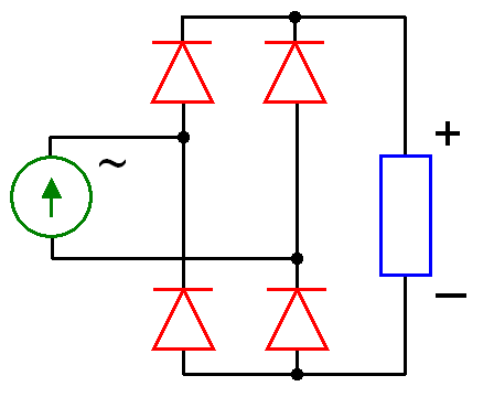
The pulsating DC output from a rectifier isn't smooth enough for most electronics. It's typically followed by a filtering stage, often using a capacitor, to smooth out the ripples and create a steady DC voltage.
What is the depletion region in a P-N junction?
When a diode is in forward bias, what happens to its internal structure and the flow of current?
Diodes are fundamental building blocks, acting as traffic cops for current in circuits. From simple rectification to precise voltage control, their one-way nature is essential to modern electronics.