Mastering ComfyUI Workflows
Node Logic Basics
The Logic of the Graph
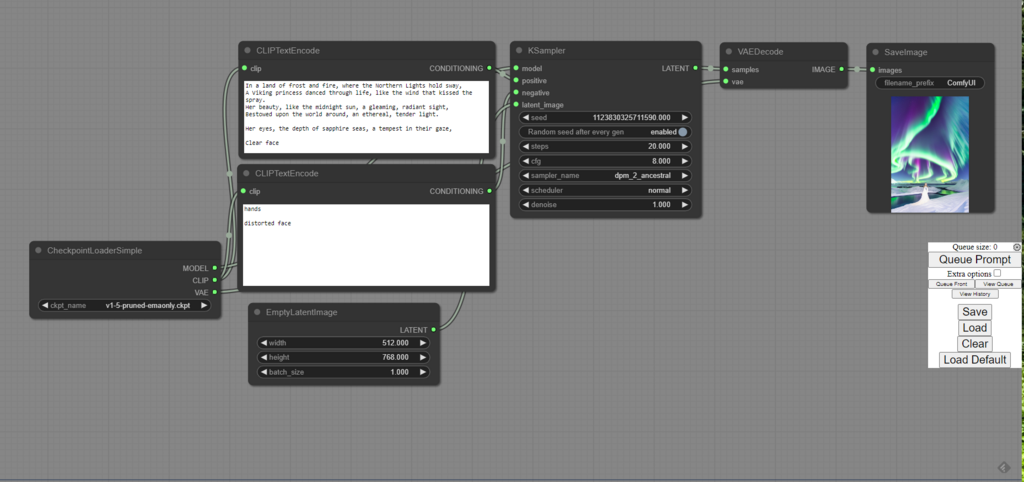
ComfyUI operates on a simple principle: data flows from left to right through a series of nodes. Think of each node as a specialised worker on an assembly line. One worker loads the raw materials (the checkpoint model), others interpret the instructions (the prompts), another does the heavy lifting of shaping the product (the KSampler), and a final one puts on the finishing touches (the VAE Decode).
The graph executes based on these connections. A node won't start its job until it has received all the necessary inputs from the nodes connected to its left. Once it finishes, it passes its output to the right. The process starts with the 'Queue Prompt' button, which triggers the entire chain of events, starting from the furthest-left nodes and moving progressively to the right until a final image is produced.
Sockets and Data Types
The inputs and outputs on each node are called sockets, and their colours tell you what kind of data they handle. You can only connect sockets of the same colour. This system prevents you from, for example, plugging raw image data where the main model is expected.
| Colour | Data Type | Description |
|---|---|---|
| Pink | MODEL | The main diffusion model from the checkpoint file. |
| Yellow | CLIP | The language model used to interpret your text prompts. |
| Orange | VAE | Translates between pixel space and latent space. |
| Purple | LATENT | The image data in its compressed, mathematical form (latent space). |
| Blue | CONDITIONING | The prompt, converted into instructions the MODEL can understand. |
| Green | IMAGE | The final image data in pixels that you can see. |
Building a Basic Workflow
Let's build the default workflow from scratch to see how these parts interact. We begin with the Load Checkpoint node. This is our starting point, providing the three core components from the model file: the MODEL, the CLIP model, and the VAE.
Next, we need to process our prompts. We'll use two CLIP Text Encode nodes, one for the positive prompt and one for the negative. We connect the yellow CLIP output from our checkpoint node into the yellow CLIP input of both these prompt nodes. These nodes take our text and, using the CLIP model, convert it into a format called conditioning. This is essentially the set of instructions our main model will follow.
Now for the main event: the KSampler node. This is where the image is actually generated. It requires several inputs:
- model: The pink MODEL output from the checkpoint.
- positive: The blue CONDITIONING output from our positive prompt node.
- negative: The blue CONDITIONING output from our negative prompt node.
- latent_image: This needs a starting point. We use an
Empty Latent Imagenode to provide a blank canvas in latent space, specifying the desired height and width.
The KSampler works its magic by taking the random noise from the empty latent image and gradually denoising it, following the instructions from the positive conditioning and avoiding what's in the negative conditioning. The result is a finished image, but it's still in the abstract latent space format.
To see our final product, we need the VAE Decode node. This node takes the latent image output from the KSampler and the VAE model from our Load Checkpoint node. It acts as a translator, converting the abstract data back into the pixels we can see. The final green IMAGE output can then be connected to a Save Image or Preview Image node.
Now that you understand the flow, let's test your knowledge.
What is the fundamental principle of how a workflow is executed in ComfyUI?
In ComfyUI, you can connect an input socket to an output socket regardless of their colour.
That's the fundamental logic of a ComfyUI graph. Every workflow, no matter how complex, is built upon this core principle of data flowing through connected nodes.