ESP32 IoT Device Architecture and Development
ESP32 Architecture and Pinouts
Under the Hood of the ESP32
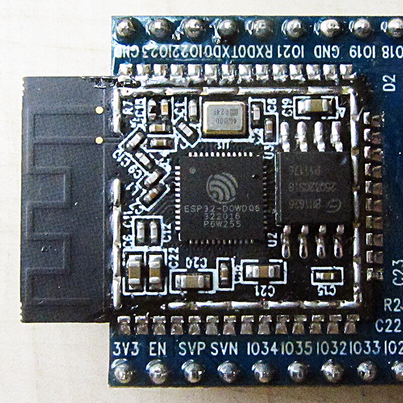
The ESP32 isn't just a single-core processor. It's built around a , which means it has two independent processing cores. Think of it as having two brains. One core can handle demanding tasks like managing a Wi-Fi connection, while the other is free to run your application code, like reading sensors or updating a display. This separation prevents a network slowdown from making your whole project unresponsive.
The Pin Juggling Act
Most microcontrollers have pins with fixed functions. Pin 5 is always for this, pin 10 is always for that. The ESP32 is more flexible thanks to its GPIO Matrix. Almost any digital peripheral, like I2C, SPI, or UART, can be routed to almost any General-Purpose Input/Output (GPIO) pin. This is called and it's a lifesaver for complex projects or when designing a custom circuit board (PCB). You're not locked into a rigid pinout.
This flexibility comes with a few rules. Some pins have special jobs, especially when the chip first powers on.
Boot-Up and Special Pins
When an ESP32 boots, it needs to know what to do. Should it run the code you uploaded, or should it wait for new code? It figures this out by checking the voltage level on a few specific pins called the instant it gets power.
If these pins are pulled high or low unexpectedly by external components, the ESP32 might refuse to start or enter the wrong mode. It's crucial to be mindful of what's connected to them.
| Pin | Default State | Notes |
|---|---|---|
| GPIO 0 | Pulled High | Must be LOW to enter bootloader (flashing) mode. |
| GPIO 2 | Pulled Low | Must be LOW on boot for normal execution. |
| GPIO 5 | Pulled High | Determines SDIO slave timing. Keep HIGH for normal use. |
| GPIO 12 | Pulled Low | Sets flash voltage. Do not pull HIGH on boot. |
| GPIO 15 | Pulled High | Controls boot logging. Keep LOW for normal use. |
Best practice: Avoid using strapping pins for inputs like buttons or for components that might have an unpredictable state at power-on.
Reading the Analog World
The ESP32 has two Analog-to-Digital Converters (ADCs) to read analog signals, like from a potentiometer or temperature sensor. They are not identical, however. ADC1 is the general-purpose workhorse. ADC2, on the other hand, shares hardware with the Wi-Fi driver.
The third part focuses on working with two commonly used peripherals, namely GPIO and I2C.
What does this mean for your project? When Wi-Fi is active, you cannot reliably use ADC2. The Wi-Fi radio takes priority, and any attempt to read from an ADC2 pin will likely fail or return junk data. If your project needs both Wi-Fi and analog readings, stick to the pins connected to ADC1.
Finally, the ESP32 packs some interesting sensors right onto the chip itself. You get access to several capacitive touch pins, which can detect a finger's touch without any moving parts, perfect for simple user interfaces. It also includes a built-in which can detect changes in magnetic fields. This is useful for things like detecting if a lid with a small magnet is open or closed, or for measuring the rotation of a spinning object.
Ready to check your understanding of the ESP32's unique features?
What is the main advantage of the ESP32's Xtensa dual-core architecture?
You are designing a project that requires both Wi-Fi connectivity and reading an analog sensor. Which of the following is a critical consideration for the ESP32?
Knowing these architectural details helps you choose the right pins and avoid frustrating bugs, laying a solid foundation for building robust and reliable IoT devices.