
Controls engineering that includes vision, data bases, plc, etc
Welcome! I'm excited to dive into the world of industrial automation with you. Since we're covering a complete ecosystem—from physical controllers on the factory floor all the way to cloud-connected databases—it helps to tailor our focus to your background so we can make this as valuable as possible.
To get us started on the right foot, what is your current background in engineering or programming, and do you have a specific project or career goal in mind?
I'm an electrical engineer looking to specialize in systems integration.
Welcome to the program! It's fantastic to have an electrical engineer here. Your background in circuit design, industrial power, and signal flow is the perfect launchpad for mastering .

To help us map out our journey, let's start by laying down our roadmap using the Automation Pyramid, which is the classic framework engineers use to structure how factory floor devices talk to enterprise databases. Since we have a clear path ahead, let's look at how our learning session is structured.
As we step into our first topic, we want to look at how a modern automated factory is organized. Rather than being a chaotic web of wires, industrial systems are structured in a clean, hierarchical stack known as the . Let's break down this pyramid so you can see exactly where PLCs, vision systems, and databases fit.
Continue to the Automation Pyramid layers
Let's dive straight into the structural core of industrial systems: the Automation Pyramid. As an electrical engineer, you are probably used to thinking about signals traveling from a physical sensor to a controller. The pyramid simply expands this concept into a standard, five-layer corporate and industrial network designed to prevent data chaos.
The Five Layers of the Automation Pyramid
In systems integration, we organize every device and piece of software into five distinct hierarchical layers, numbered Level 0 through Level 4. This structure is formally defined by the , an international standard for integrating enterprise and control systems.
| Layer Level | Layer Name | Key Components & Technologies | Real-World Function |
|---|---|---|---|
| Level 0 | Field Level | Sensors, Actuators, Motors, Solenoids | Physical execution and raw signal generation |
| Level 1 | Control Level | PLCs, PID Controllers, Smart Cameras | Real-time, deterministic logic execution |
| Level 2 | Operations / SCADA Level | HMIs, SCADA Systems, Local Client Nodes | Operator visualization and localized monitoring |
| Level 3 | MES Level | Execution Software, Production Historians | Tracking batch runs, overall equipment effectiveness (OEE) |
| Level 4 | Enterprise Level | ERP Systems (SAP, Oracle), Business Databases | Inventory logistics, sales ordering, corporate scheduling |
Think of the data flow like a pipeline: Level 0 generates raw physical voltages or currents, which Level 1 translates into digital variables and decisions. Level 2 aggregates those variables to show an operator what's happening. Level 3 evaluates how efficiently those steps ran, and Level 4 decides how many finished goods to sell based on corporate demand.
To make sure this hierarchy makes complete sense, let's look at how the physical hardware interfaces with software across these boundaries. I've initiated a diagram to help visualize how physical signals are processed upward through this exact hardware stack.
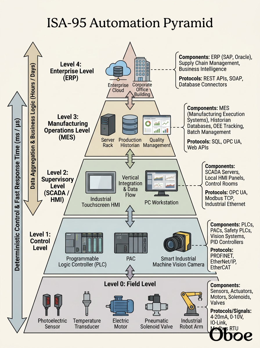
With your background in electrical engineering, you'll love how these boundaries are physically bridged. Level 0 to Level 1 is typically raw wiring ($0-10V analog lines, 24V discrete lines), whereas moving from Level 1 to Level 2 requires stepping up to digital networking protocols.
Continue to mapping components to the pyramid layers
Now that we have mapped out the overall layers of the Automation Pyramid, let's explore how we actually populate those tiers by mapping our critical hardware and software components to their proper levels.
Where Components Live in the Architecture
- PLCs (Programmable Logic Controllers): These live at Level 1 (Control Level). They act as the local brain, executing rapid logic cycles to control motors and valves based directly on raw electrical input signals.
- HMIs (Human-Machine Interfaces): These bridge Level 1 and Level 2. They are typically operator screens mounted directly on or near a machine panel, giving physical operators a localized window into the PLC's memory registers.
- Smart Cameras & Vision Systems: Depending on their design, these can span Level 0 and Level 1. A simple photo-eye sensor is pure Level 0, but a smart camera running pattern-matching algorithms to detect defects acts as a fast, localized controller, placing its decision-making logic squarely in Level 1.
- SCADA (Supervisory Control and Data Acquisition): This is the heart of Level 2. Unlike a localized HMI, SCADA monitors the entire plant floor, aggregating data from dozens of PLCs, managing system-wide alarms, and logging data.
- Databases & MES: These occupy Level 3. This is where we transition from real-time operational control to transactional data, tracking historical runs, managing recipes, and tracking quality metrics over time.
To make this concrete, let's look at how a single bottle moves through an automated bottling line, passing data vertically up through these exact components.
A bottle moving along a conveyor belt triggering inspection and data logging across four levels of the Automation Pyramid.